Optical composite and method of manufacturing the same

a technology of optical composites and composites, applied in the field of optical composites, can solve the problems of difficult manufacturing of crts having larger sizes, inability to increase luminance as desired, and limited space required for mounting, so as to prevent the reduction of luminance, increase working efficiency, and excellent hiding properties

Inactive Publication Date: 2010-03-04
KOLON IND INC
View PDF12 Cites 10 Cited by
  • Summary
  • Abstract
  • Description
  • Claims
  • Application Information

AI Technical Summary

Benefits of technology

[0043]According to the present invention, an optical composite can be provided, in which a light diffusion member and an optical sheet are integrated with each other through adhesion, thereby increasing working efficiency, and an air layer is included, thus preventing luminance from being decreased.
[0044]In addition, an optical composite can be provided, in which adhesion portions between a light diffusion member and an optical sheet are regularly arranged to thus induce an optical illusion effect so that scratches or stains cannot be seen clearly.
[0045]In addition, an optical composite for exhibiting excellent hiding properties while uniformly diffusing light emitted from a light source can be provided.
[0046]Also, an optical composite having sufficiently increased luminance due to the stable formation of an air layer and a method of manufacturing the same can be provided, and thus, there is no need to additionally use optical films or prism sheets for increasing luminance, thereby decreasing manufacturing costs, simplifying the manufacturing process, and realizing thinner displays.
[0047]Moreover, according to the present invention, in a method of manufacturing an optical composite, luminance is not decreased even in the presence of the adhesion portion, and an optical illusion effect is induced, so that scratches or stains cannot be seen clearly.

Problems solved by technology

Conventionally, a CRT (Cathode Ray Tube), which is bulky, was widely used therefor, but faces considerable limitations in terms of the space required to mount it, thus making it difficult to manufacture CRTs having larger sizes.
In these cases, although cost or productivity was improved, luminance was not increased as desired.
Further, in the course of assembling a backlight unit, scratches may occur, and some limitations are imposed on hiding properties because the light source must transmit light even though it is hidden.
Furthermore, in the course of lamination of the sheets, it is impossible to completely eliminate the fear of causing stains by light interference.
If the adhesion process is conducted using the adhesive as above, stains may be formed due to the adhesive.

Method used


Image

  • Optical composite and method of manufacturing the same
  • Optical composite and method of manufacturing the same
  • Optical composite and method of manufacturing the same

Examples


example 1

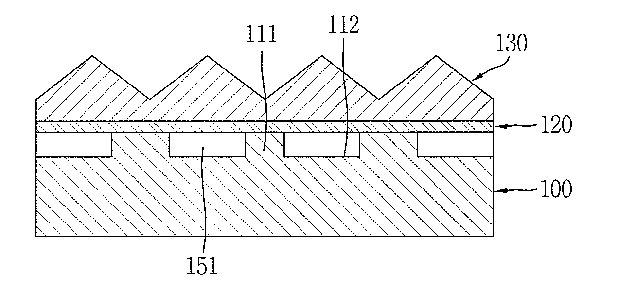
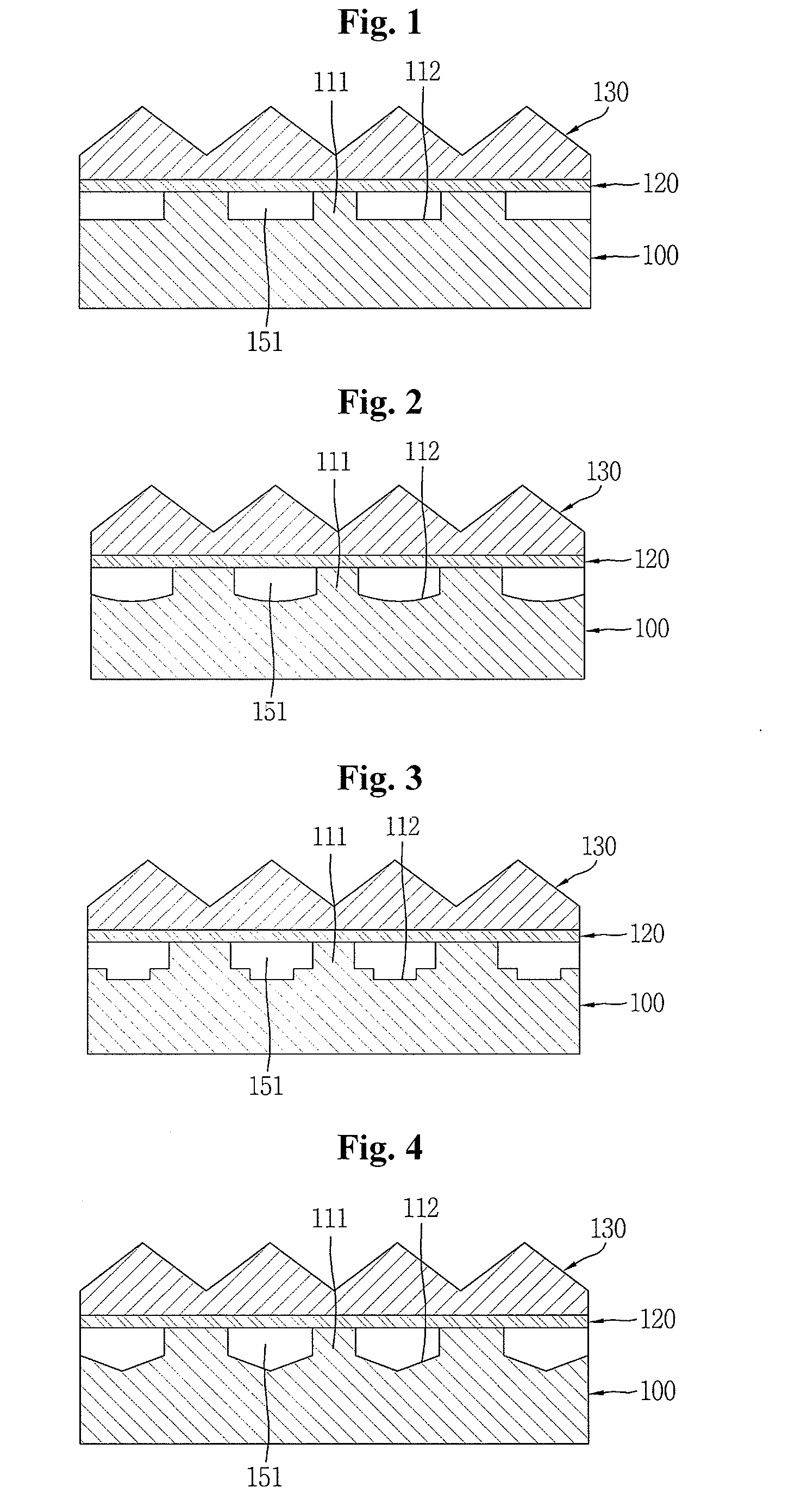
[0091]One surface of a structural layer (TT: 70%, haze: 99%) formed of polymethylmethacrylate and having a thickness of 2.0 mm was patterned through a process such as laser cutting so that 3D structures were spaced apart from each other at intervals of 100 μm to thus form an air passage in a shape having a height of 50 μm at the deepest portion and a width of 100 μm, as illustrated in FIG. 2, thus completing the structural layer.

[0092]A piece of double-sided tape (manufacturing company: Sumiron, model name: TG4191, total light transmittance: 99%, refractive index: 1.49, thickness: 25 μm) was attached to the lower surface of a prism sheet (refractive index: 1.59, substrate film: polyethyleneterephthalate (PET), thickness: 188 μm, pitch: 50 μm, height: 25 μm) as a light-collecting layer, thus forming an adhesion portion, which was then adhered to the upper surface of the 3D structures of the structural layer, thereby manufacturing an optical composite.

example 2

[0093]Example 1 was modified such that one surface of a structural layer (TT: 70%, haze: 99%) formed of polymethylmethacrylate and having a thickness of 2.0 mm was subjected to roll transfer to thus form an air passage in a shape having a height of 50 μm at the deepest portion and a width of 100 μm, as illustrated in FIG. 3, thus completing the structural layer.

example 3

[0094]Example 1 was modified such that a structural layer was imprinted in a pattern shape as illustrated in FIG. 4 using a press. As such, the 3D structures had a width of 100 μm and a height of 50 μm at the deepest portion, and the width of the air passage was 100 μm.


PUM

PropertyMeasurementUnit
light transmittanceaaaaaaaaaa
thicknessaaaaaaaaaa
total light transmittanceaaaaaaaaaa

Abstract

Disclosed is an optical composite for use in a backlight unit of a liquid crystal display or an illumination apparatus, which is able to sufficiently increase luminance and in which adhesion portions are regularly arranged to thus induce an optical illusion effect so that scratches or stains cannot be seen clearly. A method of manufacturing such an optical composite is also provided. There is no need to additionally use optical films or prism sheets, thus making it possible to inexpensively manufacture optical devices, such as backlight units.

Description

TECHNICAL FIELD[0001]The present invention relates to an optical composite for use in a liquid crystal display, and to a method of manufacturing the same.BACKGROUND ART[0002]As industrial society has developed toward an advanced information age, the importance of electronic displays as a medium for displaying and transferring various pieces of information is increasing day by day. Conventionally, a CRT (Cathode Ray Tube), which is bulky, was widely used therefor, but faces considerable limitations in terms of the space required to mount it, thus making it difficult to manufacture CRTs having larger sizes. Accordingly, CRTs are being replaced with various types of flat panel displays, including liquid crystal displays (LCDs), plasma display panels (PDPs), field emission displays (FEDs), and organic electroluminescent displays. Among such flat panel displays, in particular, LCDs, a technologically intensive product resulting from a combination of liquid crystal-semiconductor technique...

Claims


Application Information

Patent Timeline
Patent Type & Authority Applications(United States)
IPC IPC(8): B32B3/00G02B5/02B29C47/02B29C48/08B29C48/12B29C48/154
CPCB29C47/0021B29C47/003B29C47/025B29K2025/00B29K2033/12B29K2069/00Y10T428/24612G02B5/0215G02B5/0221G02B5/0231G02B5/0242G02B5/0278G02B5/045B32B3/30B32B7/12B32B27/08B32B27/18B32B27/26B32B27/302B32B27/308B32B27/36B32B27/365B32B27/38B32B27/40B32B27/42B32B3/26B32B3/28B32B2264/0214B32B2264/0235B32B2264/025B32B2264/0257B32B2264/10B32B2264/102B32B2270/00B32B2307/40B32B2307/412B32B2457/202B29C48/08B29C48/12B29C48/154
Inventor CHO, YOON HEELEE, HEE CHEONGLEE, HYUNG SOO
Owner KOLON IND INC
Why Eureka
Try Eureka