Information processing apparatus and method

Inactive Publication Date: 2010-08-19
CANON KK
View PDF9 Cites 24 Cited by
  • Summary
  • Abstract
  • Description
  • Claims
  • Application Information

AI Technical Summary

Benefits of technology

[0009]According to the present invention, the existing operational settings of an image forming apparatus can be carried over, as a result of which it is possible to reduce the operational burden and prevent erroneous settings. Furthermore, an image forming apparatus that has operational setting

Problems solved by technology

Under such circumstances, when the user wants to use the same settings as those within the MFP used before personnel changes, such as button data, in the newly registered MFP, or when the MFP used before personnel changes and the newly registered MFP have the same functions, it is very frustrating for the user to create new button data and register the button data in the newly registered MFP.
In addition, if all of the settings registered in an

Method used


Image

  • Information processing apparatus and method
  • Information processing apparatus and method
  • Information processing apparatus and method

Examples


embodiment 1

[0029]Hereinafter, best modes for carrying out the present invention will be described with reference to FIGS. 1 to 17.

[0030]System Configuration

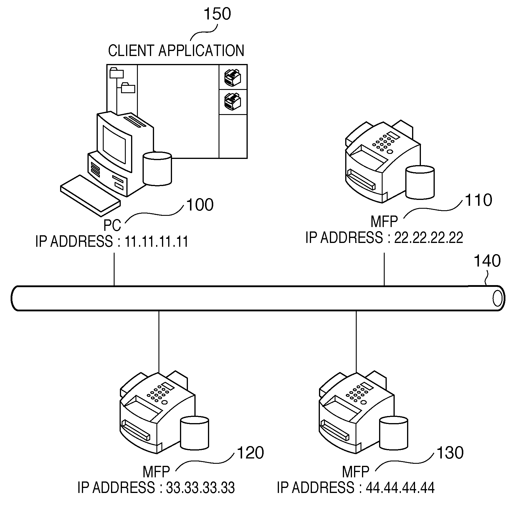
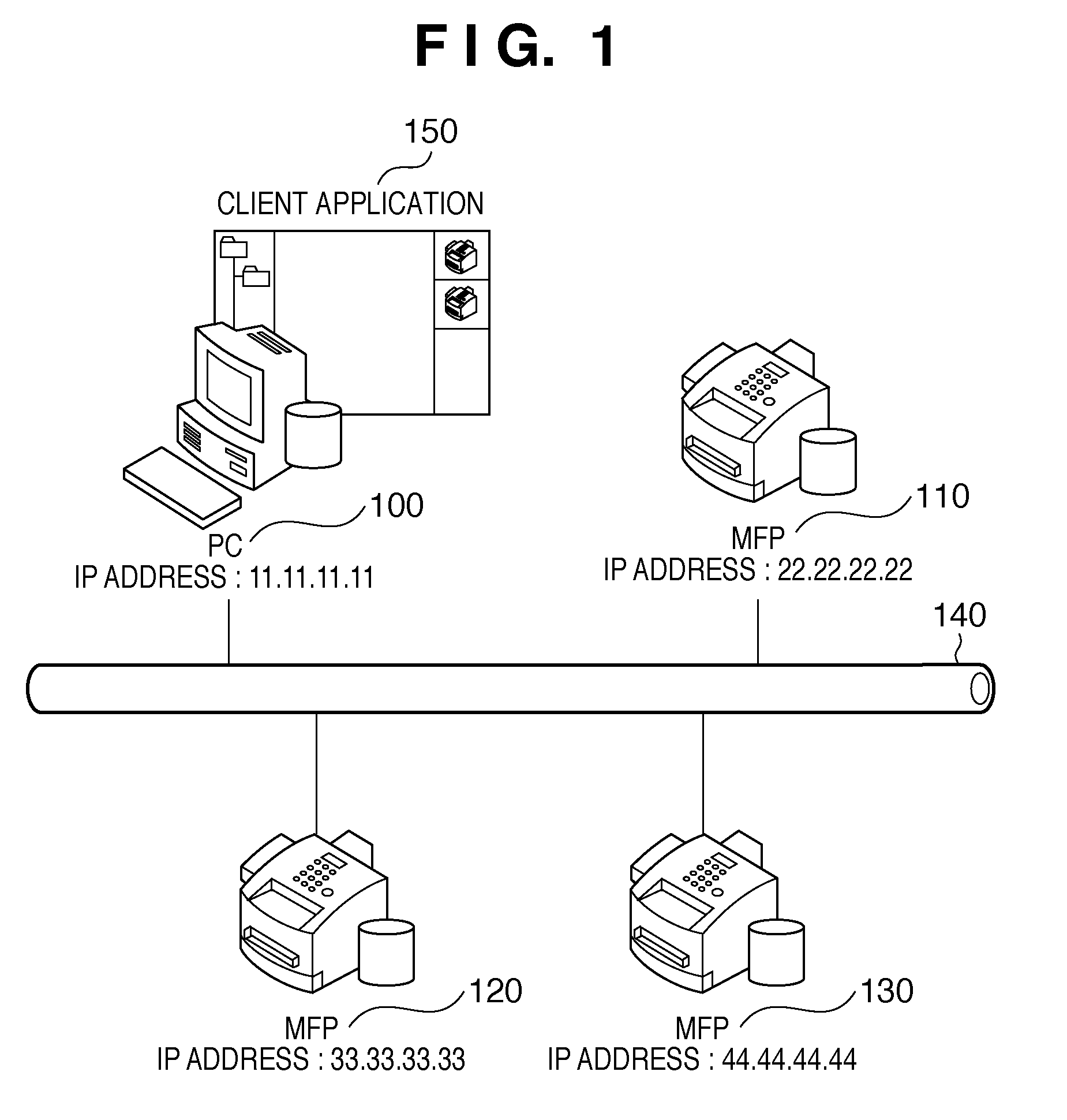
[0031]FIG. 1 is a conceptual diagram of a system in which an information processing system according to the present embodiment is applied. A PC (corresponding to an information processing apparatus) 100 and MFPs (corresponding to image forming apparatuses) 110, 120 and 130 are connected to a network via a LAN 140. In the PC 100, a client application 150 dedicated to the image forming system of the present invention is installed. The PC 100, the MFP 110, the MFP 120 and the MFP 130 are assumed to have IP addresses “11.11.11.11”, “22.22.22.22”, “33.33.33.33” and “44.44.44.44”, respectively. The IP addresses are used as identification information or identifiers of the apparatuses.

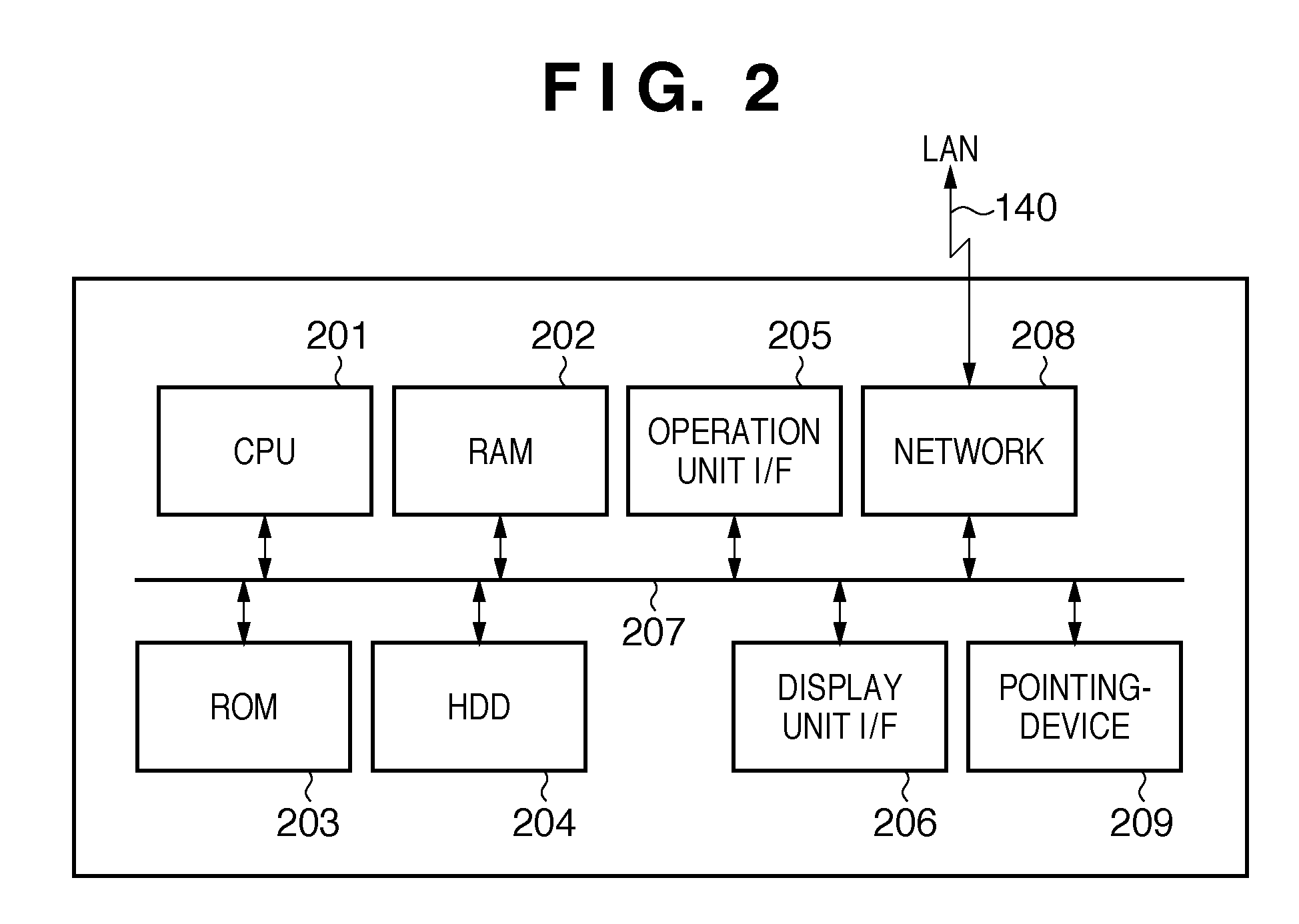
[0032]Hardware Configuration

[0033]FIG. 2 is an example of a hardware configuration diagram of a PC that constitutes the information processing system according to the...

embodiment 2

[0073]Embodiment 2 of the present invention will be described with reference to FIG. 18. Embodiment 2 differs from Embodiment 1 in the process for registering button data. In Embodiment 1, when registering button data, the button data is appended to a button data registration request and then transmitted. In Embodiment 2, a button data ID and the IP address of a transfer source device are appended to a registration request, and button data is transferred between devices. Other configurations are the same as Embodiment 1, so a description there of is omitted here.

[0074]FIG. 18 is a procedure of data processing of the client application 150, a newly registered device and a transfer source device performed so as to register button data in an information processing system of the present embodiment.

[0075]In S1801, the external settings processing unit 407 makes a request to register button data to be transferred as instructed via the communication unit 403. The external settings processi...


PUM


Abstract

A situation can occur in which the seating location of a user is moved due to personnel changes within a division or the like, and the user has to use a different nearby image forming apparatus. In such a case, with conventional technology, it is not possible to efficiently transfer the settings information used in an image forming apparatus used before the personnel change to the new nearby image forming apparatus. According to the present invention, when an instruction to register an image forming apparatus is made in an application by the user, settings information set by the user is searched for in the image forming apparatuses that are registered in the application and the image forming apparatuses that were deleted from the application in the past, and they are presented as transfer candidates.

Description

BACKGROUND OF THE INVENTION[0001]1. Field of the Invention[0002]The present invention relates to an information processing apparatus and method for transferring settings information registered in, for example, an image forming apparatus or the like to another image forming apparatus.[0003]2. Description of the Related Art[0004]In a conventional MFP (Multi Function Peripheral) that has a copy function, a print function and a facsimile transmission function and so on, macros that execute frequently used settings and a series of processes can be registered as buttons, whereby the user can perform a desired process with a simple operation, just pressing a button registered on a user interface of the MFP, without the need to set complicated settings each time. In addition, an application is also provided that is capable of creating button data with the use of a keyboard and a mouse of a PC (personal computer) and registering the button data in an MFP. Because of the use of a keyboard and...

Claims


Application Information

Patent Timeline
IPC IPC(8): G06F15/00
CPCG06F3/1285G06F3/1286G06F3/1204G06F3/1257G06F3/1209G06F3/1225G06F3/1205
Inventor SATO, TETSUYA
Owner CANON KK
Why Eureka
Try Eureka