Structure for controlling optical zoom distance via magnetic lines of force

Inactive Publication Date: 2010-08-19
CHAO LI MING
View PDF2 Cites 34 Cited by
  • Summary
  • Abstract
  • Description
  • Claims
  • Application Information

AI Technical Summary

Benefits of technology

[0007]A main object of the present invention is to provide a structure for controlling optical zoom distance via magnetic lines of force, which can ac

Problems solved by technology

The conventional electric torches have shells formed by combining a bulb housings and a main housing closely, and cannot adjust focusing/defocusing light sources.
Accordingly, if the electric torches is operated carelessly or the seal rings are aged, worn, or there are foreign bodies in the structure, the gap

Method used


Image

  • Structure for controlling optical zoom distance via magnetic lines of force
  • Structure for controlling optical zoom distance via magnetic lines of force
  • Structure for controlling optical zoom distance via magnetic lines of force

Examples


Embodiment Construction

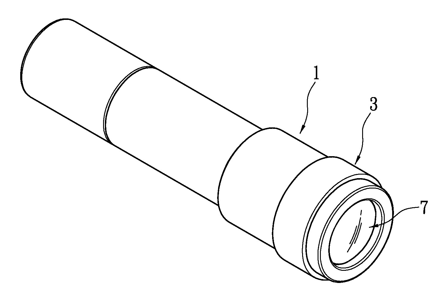
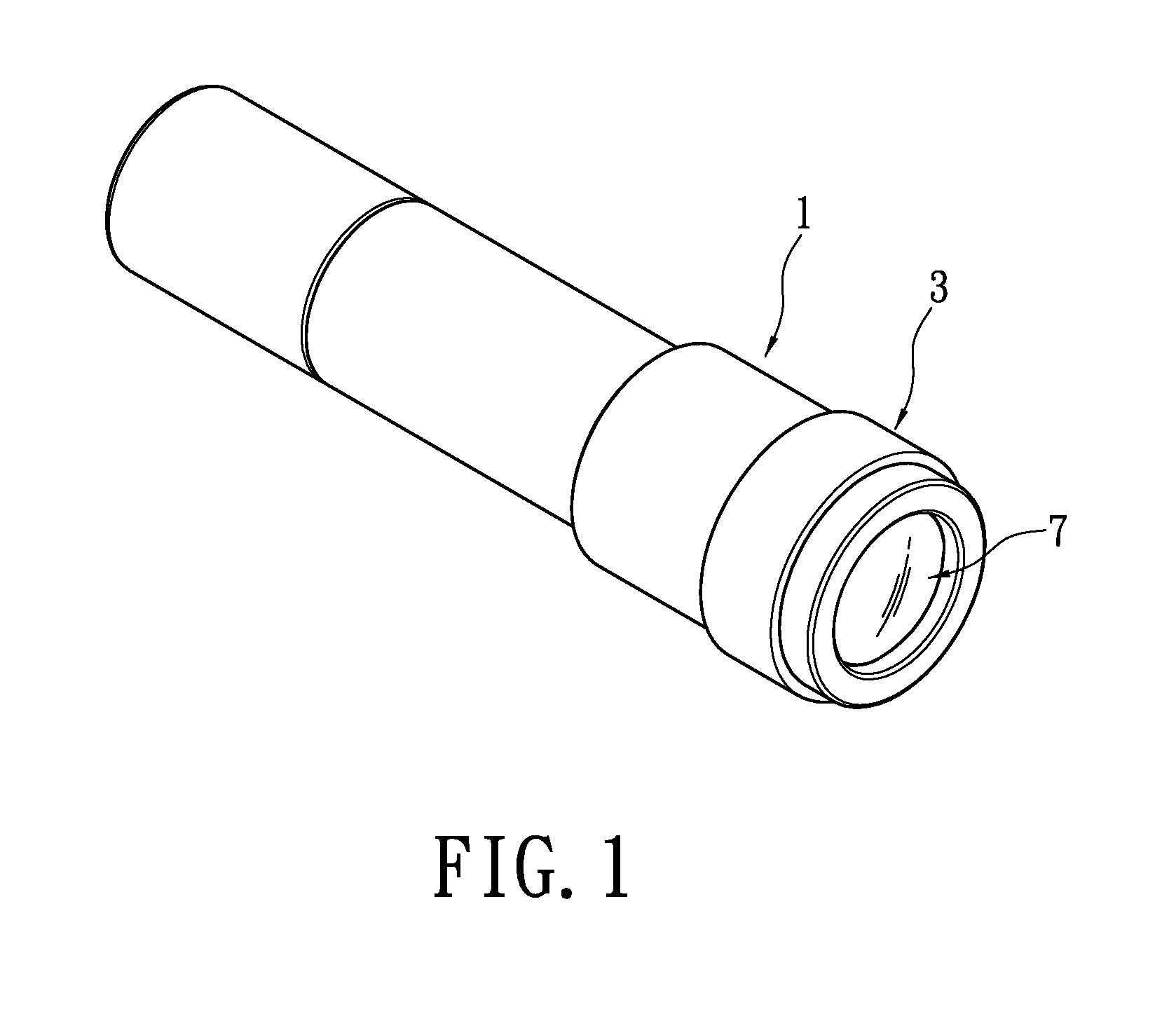
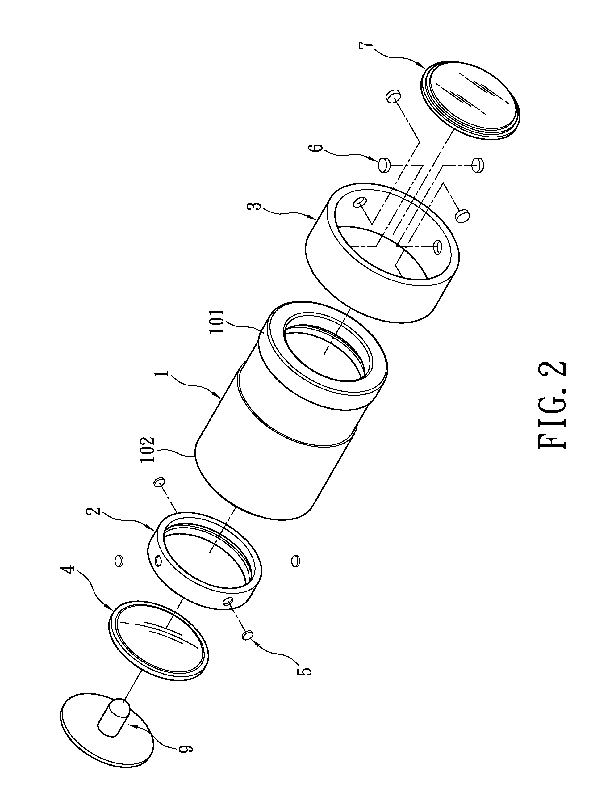
[0021]Please refer to FIGS. 1-3 illustrating a structure for controlling optical zoom distance via magnetic lines of force according to the present invention, which may be applied in optical zoom devices such as electric torches, lighting lamps and so on. In the embodiment, the structure is used in an electric torch. The structure includes a closed shell 1, a controlled member 2, a controlling member 3, a zoom device 4, at least one first magnetic element 5 and at least one second magnetic element 6.

[0022]The closed shell 1 is one portion of a main body of the electric torch, and the closed shell 1 forms the portion of the main body of the electric torch via assembly or integral forming. The closed shell 1 has at least one light source 9 disposed therein, which may be a visible light emitting diode (LED), a bulb or an invisible light emitting diode, etc. A lens 7 and a seal ring made of a plastic soft material 8 are disposed in a front end 101 of the main body of the electric torch;...


PUM


Abstract

A structure for controlling optical zoom distance via magnetic lines of force, which is applied in electric torches, lighting lamps and so on, includes a closed shell, a controlled member, a controlling member, a zoom device, a first magnetic element and a second magnetic element. The controlled member is movably disposed in the closed shell. The controlling member is movable disposed outside the closed shell. The zoom device is disposed on the controlled member. The first magnetic element is disposed on the controlled member and the second magnetic element is disposed on the controlling member. Based on the structure, the present invention can achieve optical zoom.

Description

BACKGROUND OF THE INVENTION[0001]1. Field of the Invention[0002]The present invention relates to an optical zoom distance structure, and more particularly to an optical zoom distance structure which is applied in electric torches, lighting lamps and so on, and controls optical zoom distance via magnetic lines of force.[0003]2. Description of Related Art[0004]Electric torches are one kind of lighting tool and generally divided into two categories: conventional electric torches and variable-focus electric torches. The conventional electric torches have shells formed by combining a bulb housings and a main housing closely, and cannot adjust focusing / defocusing light sources. The variable-focus electric torches can adjust focusing / defocusing light sources. Based on relative movements of the bulb housings and the main housing of the variable-focus electric torches, and front and rear movements of physical optical zoom elements (convex lenses or refraction lamp cups) fixed in the bulb hou...

Claims


Application Information

Patent Timeline
IPC IPC(8): G02B7/04
CPCF21L14/00F21V14/02F21V14/025F21V14/04G02B7/04F21V14/06F21V14/065F21V17/02F21V19/02F21V14/045
Inventor CHAO, LI-MING
Owner CHAO LI MING
Why Eureka
Try Eureka