
Method for eliminating scatter artefacts

a scatter artefact and scattering technology, applied in the field of eliminating scatter artefacts, can solve the problems of affecting the reporting of absolute hounsfield units, affecting the accuracy of scatter artefacts, and affecting the accuracy of scatter artefacts, and achieving the effect of reducing scatter artefacts, reducing scatter artefacts, and reducing scatter artefacts

Inactive Publication Date: 2010-08-19
KONINKLIJKE PHILIPS ELECTRONICS NV
View PDF7 Cites 27 Cited by
  • Summary
  • Abstract
  • Description
  • Claims
  • Application Information

AI Technical Summary

Benefits of technology

[0009]It is therefore an object of the present invention to provide a method and an apparatus as well as a corresponding computer program for eliminating scatter artefacts that corrupt an image of an object.
[0010]The object is achieved according to the present invention by a method for eliminating scatter artefacts that corrupt an image of an object using computed tomography, wherein X-ray projections of the object are at least partially truncated, comprising the steps of:reconstructing a truncated image of the object with a limited field of view from the projections;constructing a model of the object in an extended field of view using the truncated image of the object;deriving a scatter estimate by means of Monte-Carlo simulation using the model of object;correcting a projection of the object for X-ray scatter based on the scatter estimate;reconstructing a scatter-corrected image using the corrected projections.

Problems solved by technology

Scattered radiation is a major source of image degradation and non-linearity in cone-beam computed tomography.
As a consequence, reconstructed volumes suffer from cupping and streak artefacts due to scatter, impeding the reporting of absolute Hounsfield units.
Anti-scatter-grids composed of lead lamellae and interspacing material have shown to be ineffective for typical volume imaging geometries, because they increase the SNR ratio.
Additionally, even behind the grid, a large fraction of the scattered radiation is still present and therefore anti-scatter-grids are not well suited as the only means to reduce cupping and streak artefacts.
However, in case of laterally truncated projections, the above-described technique faces large problems.
Especially the reconstructable field of view covers only a fraction of the total object region and therefore the Monte Carlo simulations lack important information required to compute meaningful scatter distributions.

Method used


Image

  • Method for eliminating scatter artefacts
  • Method for eliminating scatter artefacts
  • Method for eliminating scatter artefacts

Examples


Embodiment Construction

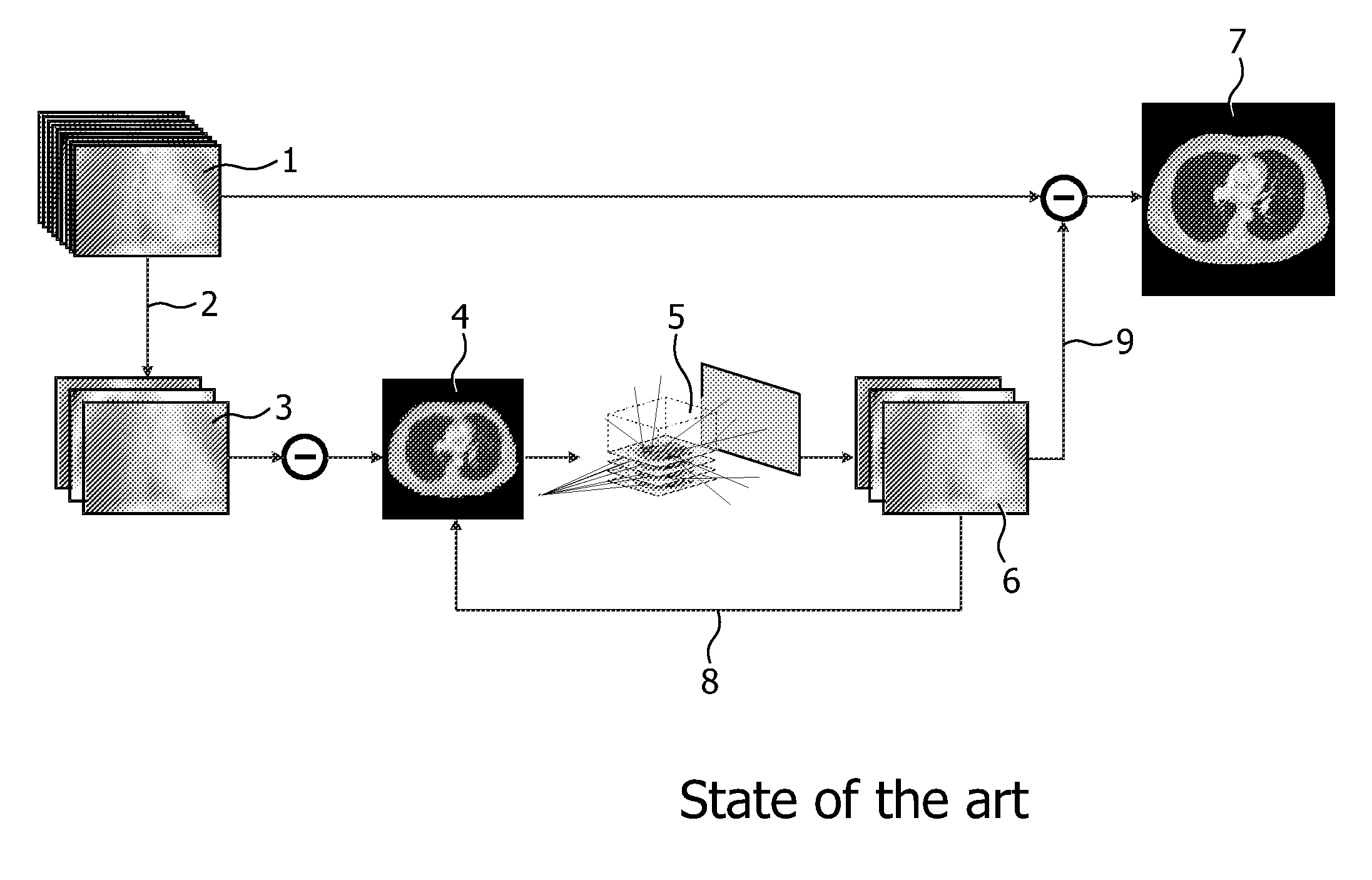
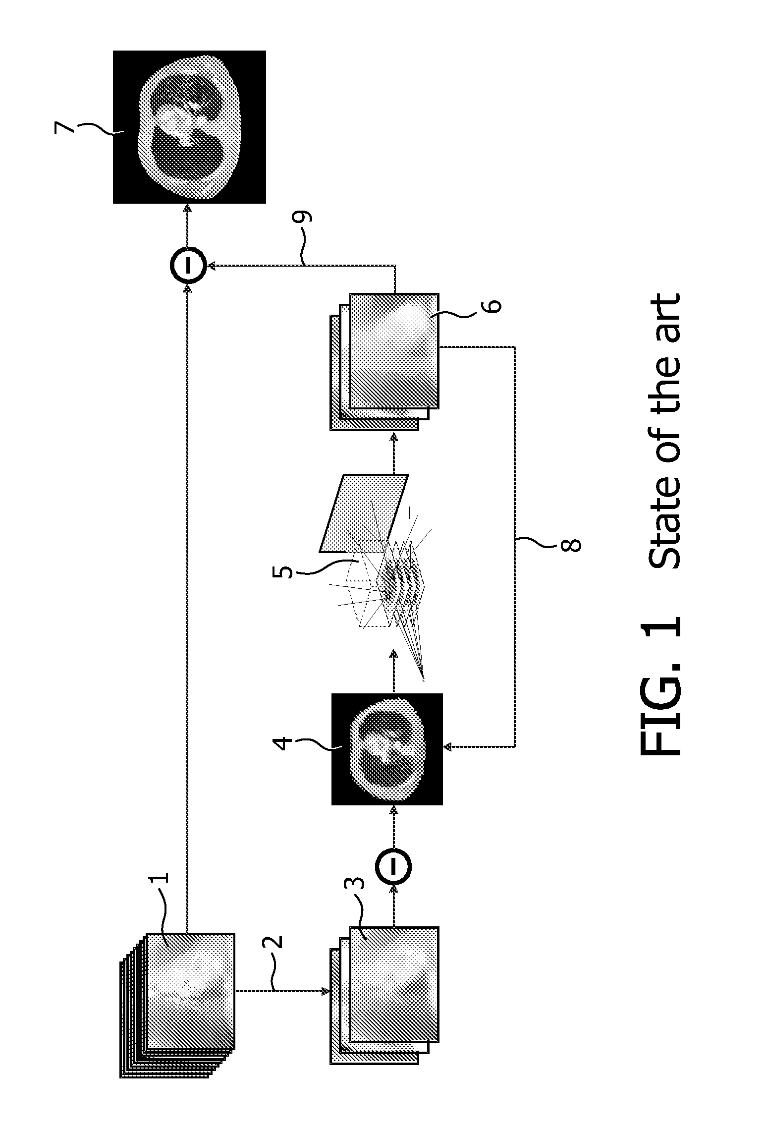
[0052]FIG. 1 shows the principle of the Monte Carlo simulation based scatter correction. Firstly, there is a full projection data set 1. This full projection data set is subsampled 2 in a coarse projection data set 3, which leads to a fast, coarse reconstruction 4. Then the Monte Carlo scatter simulation procedure is applied 5, which results in a coarse scatter data set 6. These last three steps can be repeated by iteration in order to improve accuracy. The result thereof is upsampled 9 and subtracted from the original full projection data set 1, which leads to a final reconstruction 7. This principle of Monte Carlo simulation based scatter correction is state of the art.

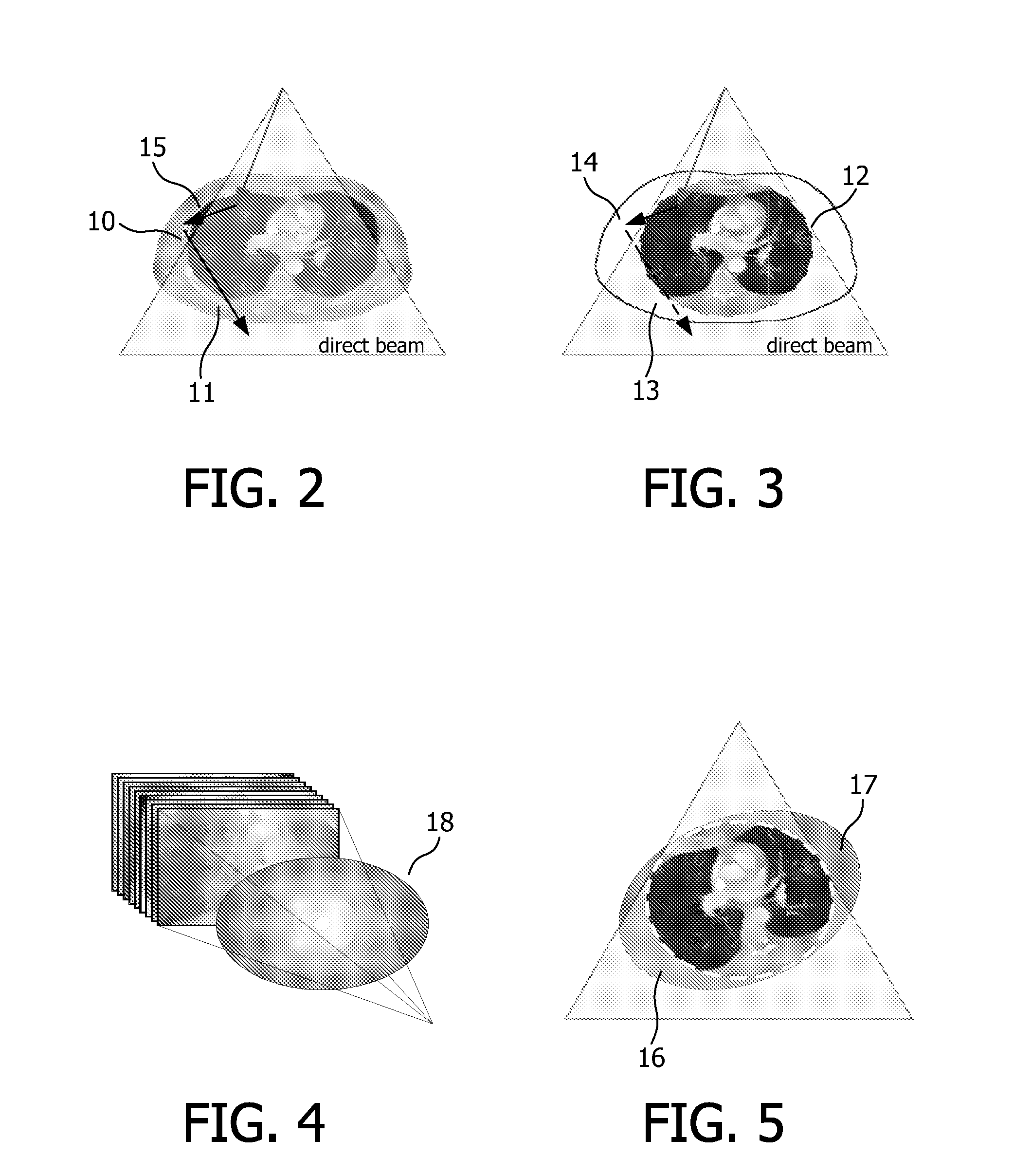
[0053]FIGS. 2 and 3 show the main error sources introduced in the Monte Carlo simulations in case the X-ray projections of the object are at least partially truncated, where only a truncated image of the object with a limited field of view can be reconstructed. First, regions missing prior and after the field of vie...


PUM


Abstract

A method, a computer program as well as a corresponding apparatus for eliminating scatter artefacts that corrupt an image of an object using computed tomography, wherein X-ray projections of the object are at least partially truncated, whereas the method comprises the steps of: reconstructing a truncated image of the object with a limited field of view from the projections; constructing a model of the object in an extended field of view using the truncated image of the object; deriving a scatter estimate by means of Monte-Carlo simulation using the model of object; correcting a projection of the object for X-ray scatter based on the scatter estimate; reconstructing a scatter-corrected image using the corrected projections.

Description

FIELD OF THE INVENTION[0001]The present invention relates to a method and a corresponding apparatus for eliminating scatter artefacts that corrupt an image of an object using computed tomography. Finally, the invention relates to a computer program for implementing the methods on a computer.BACKGROUND OF THE INVENTION[0002]The document WO 2006 / 082557 shows a model estimation unit for estimating model parameters of an object model for the object by an iterative optimization of a deviation of forward projections, calculated by use of the object model and the geometry parameters for X-ray projections from the corresponding X-ray projections as well as a scatter estimation unit for estimating the amount of scatter present in said x-ray projections by use of said object model.[0003]Scattered radiation is a major source of image degradation and non-linearity in cone-beam computed tomography. This especially applies for system geometries with large cone angle and therefore a large irradiat...

Claims


Application Information

Patent Timeline
IPC IPC(8): G06K9/00
CPCG06T11/005G01T1/1648
Inventor WIEGERT, JENSBERTRAM, MATTHIAS
Owner KONINKLIJKE PHILIPS ELECTRONICS NV
Learn More