Recording device and control method for a recording device

a recording device and control method technology, applied in the field of recording devices, can solve the problems of difficult to adapt such devices for use with recording media other than single forms such as checks, and the difficulty of printing checks after reading micr information optically, so as to eliminate unnecessary transportation operations, improve accuracy, and reduce the effect of tim

Active Publication Date: 2010-08-19
SEIKO EPSON CORP
View PDF12 Cites 7 Cited by
  • Summary
  • Abstract
  • Description
  • Claims
  • Application Information

AI Technical Summary

Benefits of technology

[0010]A recording device according to the first aspect identifies MICR information that is difficult to recognize with high accuracy by comparing the result of magnetically reading MICR information recorded on the recording medium with the result of optically reading the MICR information, and conveys the recording medium to an optical reading unit when magnetically reading the MICR information does not succeed. As a result, by not conveying the recording medium to the optical reading unit when magnetically reading the MICR information succeeds, unnecessary transportation operations may be eliminated, MICR information reading accuracy may be improved, and the processing speed may be improved.
[0011]Furthermore, because the magnetic reading unit is mounted on a first carriage at a first position along the transportation path, the recording head is mounted on a second carriage that is different than the first carriage, and the optical reading unit is disposed at a different position along the transportation path than the first and second carriages, the magnetic reading unit and the recording head can be moved mutually independently by the first and second carriages. As a result, different types of recording media, including bound media and single sheet media, can be magnetically read and images can be recorded thereon, and a single device that is compatible with a wide range of recording media can be achieved.

Problems solved by technology

A problem with such devices is that when a reading unit that reads the MICR information magnetically and a reading unit that reads the MICR information optically are both disposed in a single device, the time required to process one piece of recording medium, such as one check, is increased because the recording medium must be conveyed to both reading units.
Additionally, checks that have been printed after reading the MICR information succeeds may be difficult to read optically again.
Adapting such devices for use with recording media other than single forms such as checks, such as a bound recording media, may also be difficult.

Method used


Image

  • Recording device and control method for a recording device
  • Recording device and control method for a recording device
  • Recording device and control method for a recording device

Examples


Embodiment Construction

[0040]In the following description, various embodiments of the present invention will be described. For purposes of explanation, specific configurations and details are set forth in order to provide a thorough understanding of the embodiments. However, the present invention can be practiced without the specific details. Furthermore, well-known features may be omitted or simplified in order not to obscure the embodiment being described.

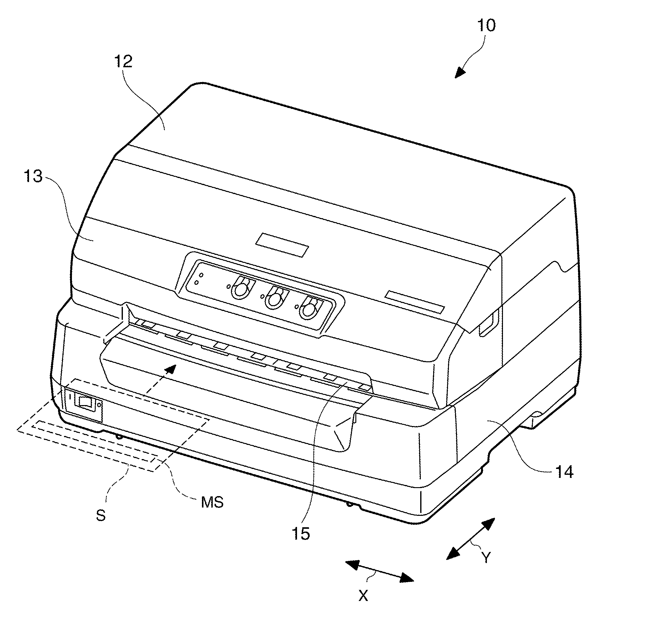
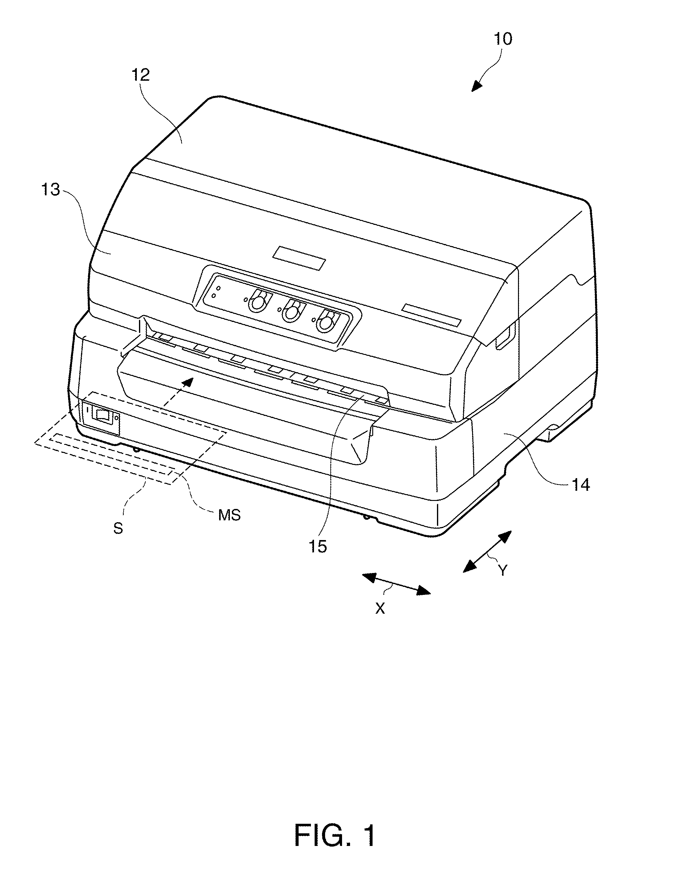
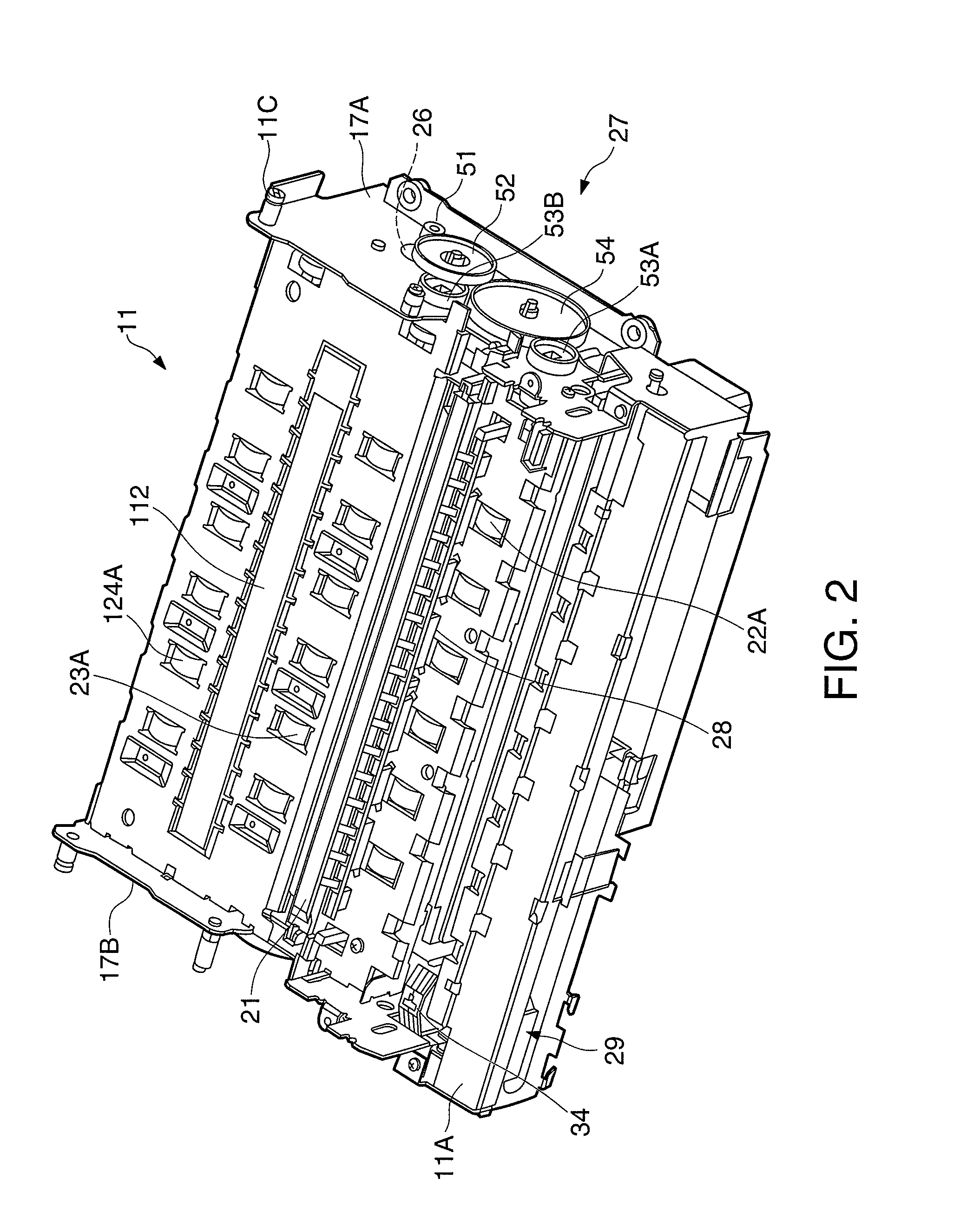
[0041]Referring now to the drawings, in which like reference numerals represent like parts throughout the several views, FIG. 1 is a front oblique view of a dot impact printer 10 as an example of a recording device in accordance with many embodiments. FIG. 2 is a front oblique view of a printer chassis 11 of the printer 10. FIG. 3 is a side section view of the dot impact printer 10 shown in FIG. 1.

[0042]The dot impact printer 10 shown in FIG. 1 as a recording device records images, including text, by pushing a plurality of recording wires disposed to a...


PUM


Abstract

A recording device and a control method for a recording device improve the accuracy of reading MICR information while also shortening the time required for recording media processing. A dot impact printer 10 has a magnetic head 34 that magnetically reads MICR information recorded on a recording medium S, a recording head 18 that is mounted on a different carriage than the magnetic head 34 and records images on the recording medium S, and a back scanner 112 that optically reads MICR information recorded on the recording medium S, disposed sequentially to the transportation path P of the recording medium S. When reading the MICR information by means of the magnetic head 34 does not succeed, the recording medium S is conveyed to the back scanner 112, the MICR information is read by the back scanner 112, the reading results are compared, and the MICR information is identified.

Description

[0001]This application claims priority to Japanese Patent Application No. 2009-032286, filed Feb. 16, 2009, the entirety of which is incorporated by reference herein.BACKGROUND[0002]1. Technical Field[0003]The present invention relates to recording devices and related methods for reading magnetic ink character recognition (MICR) information.[0004]2. Related Art[0005]Devices for reading MICR information that is recorded in magnetic ink on recording media such as checks are known. Some of these devices improve recognition accuracy by combining the result of magnetically reading the MICR information with the result of optically reading the MICR information to identify the MICR information. See, for example, Japanese Unexamined Patent Appl. Pub. JP-A-H05-258100.[0006]A problem with such devices is that when a reading unit that reads the MICR information magnetically and a reading unit that reads the MICR information optically are both disposed in a single device, the time required to pr...

Claims


Application Information

Patent Timeline
Patent Type & Authority Applications(United States)
IPC IPC(8): G06K9/00H04N1/27G06V30/224
CPCG06K7/10821G06K9/18G06K5/00G06K19/06187G06K7/1447G06Q20/04G07D7/04G07D7/0047G06V30/2253G06V30/224G06V30/10
Inventor IMAE, TOSHIHIROFUJIKAWA, MASASHIKINOSHITA, YOSHIAKIMIZUNO, MORIMICHI
Owner SEIKO EPSON CORP
Why Eureka
Try Eureka