
Rotary seamer

Inactive Publication Date: 2010-08-19
CFT PACKAGING
View PDF4 Cites 4 Cited by
  • Summary
  • Abstract
  • Description
  • Claims
  • Application Information

AI Technical Summary

Benefits of technology

[0022]An object of the present invention is to eliminate the aforesaid drawbacks and make available a rotary seamer that is particularly versatile, reliable and easy to adjust.

Problems solved by technology

Therefore, prior art seamers present some problems and limitations.
A first problem derives from the need to house lubricated bearings within the roller, to allow it to rotate easily and freely; this is disadvantageous because it compromises the hygiene of the machines and the stiffness of the roller itself.
Another problem is determined by the fact that the impact between the roller and the object to be seamed (in the moment when they come in contact) entails a deterioration of the surfaces that come in contact, with inevitable failures due to the jamming of the machine caused by the material removed in said impact.
Moreover, in use seamers present additional technical problems with respect to the actuation of the roller from the deactivated position to the operative position and vice versa.
This entails two kinds of problems.
In the first place, said mechanical adjustments are complicated and costly and they are difficult to perform with precision (because they have to be carried out manually).
Secondly, the profile of the cam has to be redesigned in relation to the situation whereto corresponds the maximum rotation of the pivot; consequently, the profile of the cam is not optimised in all other situations.
Another problem is to vary the number of seaming turns.
In this regard, while in known seamers the variation of the number of seaming turns is possible, it entails interventions that are costly in terms of time and of materials.
This solution, in addition to being disadvantageous in terms of times and costs, presents the drawback of requiring to vary the velocity of rotation of the object.
This solution does not allow to increase the number of seaming turns, for equal velocity of the object, by increasing the time during which the roller interacts with the object.

Method used


Image

  • Rotary seamer
  • Rotary seamer
  • Rotary seamer

Examples


Embodiment Construction

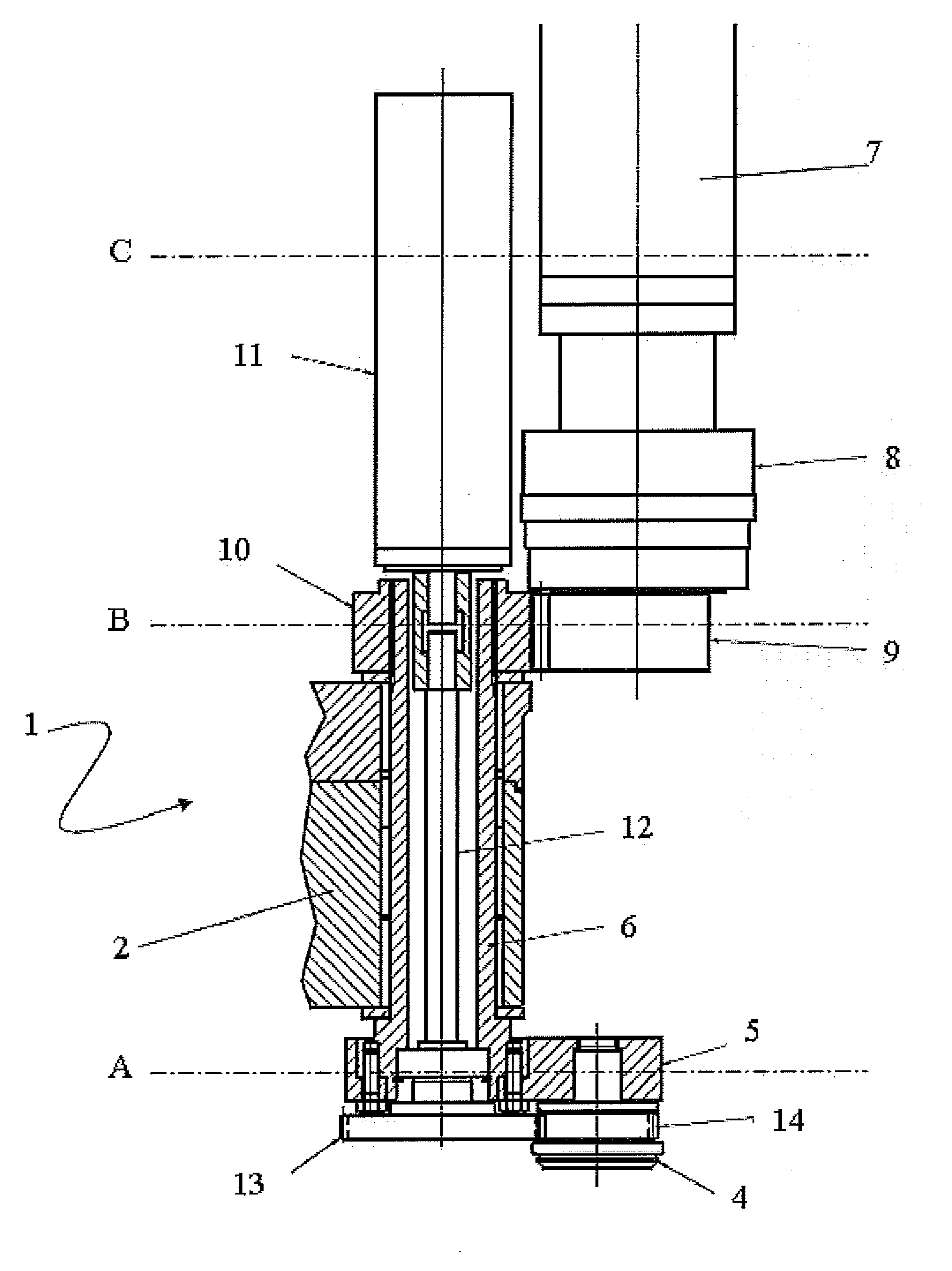
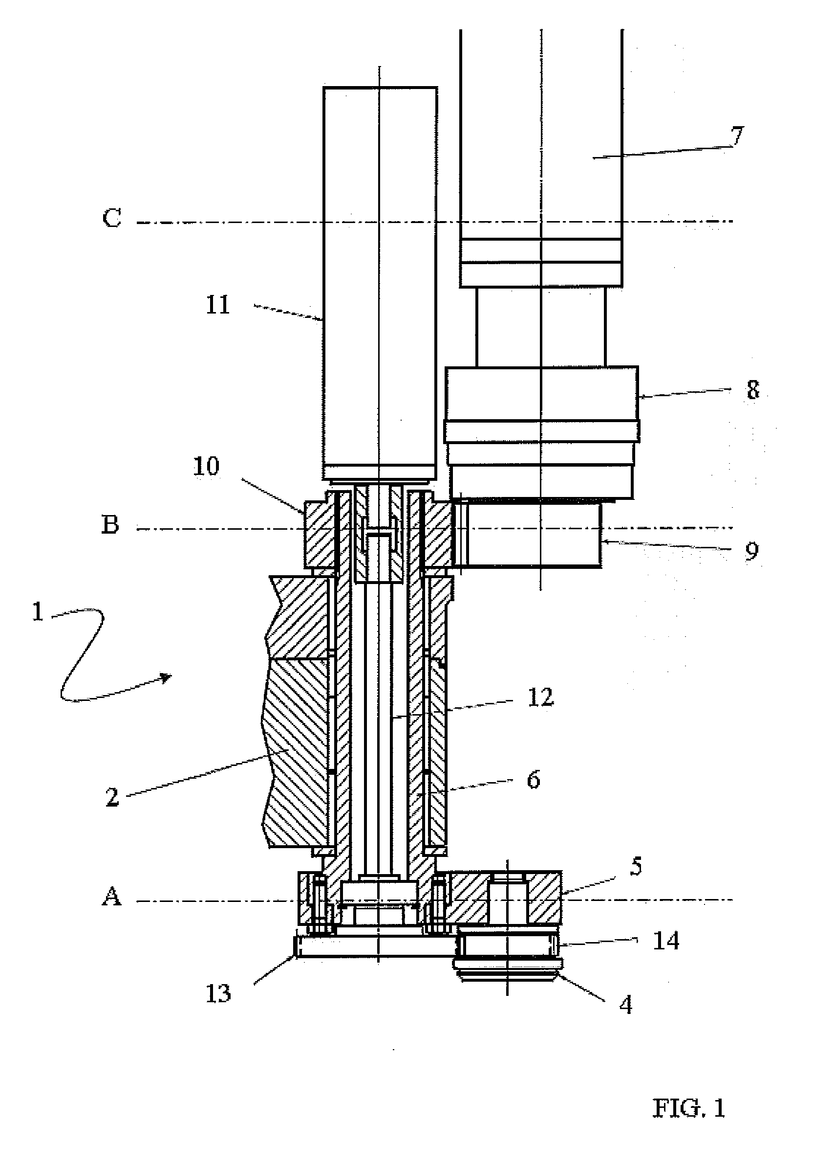
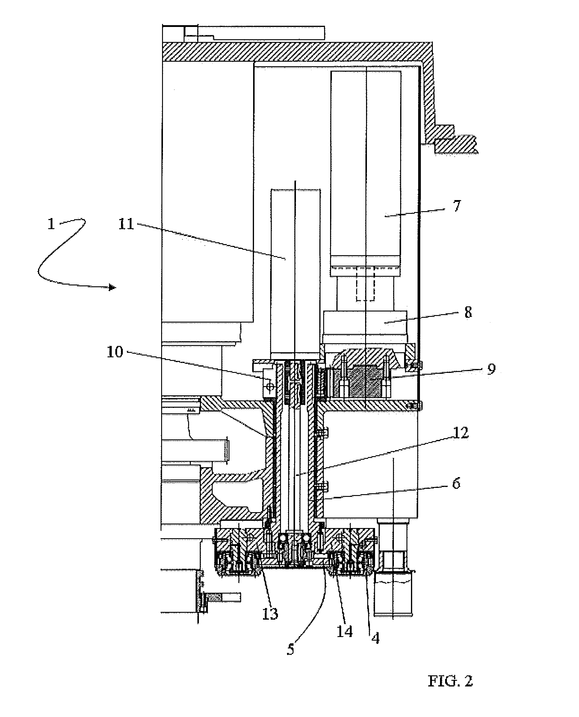
[0032]In the figures, the reference 1 indicates a seamer according to the present invention. The seamer 1 is a rotary seamer, comprising a carrousel 2 rotating around its own longitudinal axis.

[0033]To the carrousel 2 is associated a plurality of seaming stations 3; in the illustrated example (FIGS. 3-5), the seamer 1 comprises four seaming stations 3. The seaming stations 3 are substantially identical to each other and preferably positioned symmetrically on the carrousel.

[0034]FIGS. 1 and 2 show in particular one of said seaming stations 3.

[0035]The seaming station comprises a roller 4 mounted on a lever 5 integral with a rod-like element 6 rotatably coupled to the carrousel 2.

[0036]The roller 4 constitutes a seaming tool that, operatively, comes in contact with an object to be seamed positioned on a mandrel or another rotary element (not shown in the figures because it is known) associated with the carrousel 2.

[0037]The roller 4 is movable from an operative position, in which it i...


PUM

PropertyMeasurementUnit
Timeaaaaaaaaaa
Velocityaaaaaaaaaa

Abstract

A rotary seamer (1) is provided with a carrousel (2) and with at least one seaming station (3) associated with the carrousel (2) and comprising a rod-like element (6) rotating around its own longitudinal axis, a seaming tool (4) rotatably connected to a lever (5) integral with the rod-like element (6) and means for rotating the rod-like element (6) around its own longitudinal axis, in such a way as to displace the seaming tool (4) from an operative position, in which it interacts with an object seaming it, to a deactivated position, of non interference with the object, an electric actuator (11) associated with the carrousel (2) and means for connecting said electric actuator (11) to the seaming tool (4), to rotate it around its own longitudinal axis. In known seamers, the seaming tool is mounted idle on the lever, this entailing limitations and drawbacks with regard to the hygiene and reliability of the seamer.

Description

TECHNICAL FIELD AND BACKGROUND ART[0001]The present invention relates to a rotary seamer.[0002]A seamer is a machine that enables to apply a lid to a container to close it hermetically, connecting the edge of the lid to the edge of the container by folding them onto each other.[0003]Objects to be seamed generally have cylindrical geometry, e.g. they are constituted by pots or cans.[0004]In practice, seaming is achieved by setting the container in rotation around its own axis, e.g. associating it to a mandrel and making it interact with a seaming tool, which in turn is rotating and appropriately shaped, i.e. shaped in such a way as to cause said folding of the container and of the corresponding lid.[0005]In prior art solutions, the seaming tool is constituted by an idle roller. Said roller is connected to an end of a lever integral with a rotating pivot. In this way, by rotating the pivot the roller is approached to or moved away from the object, moving the roller from an operative p...

Claims


Application Information

Patent Timeline
IPC IPC(8): B21D51/26B21D51/32
CPCB21D51/26B21D51/32B65B65/02B65B57/08B65B59/02B65B7/2857
Inventor TONTI, STEFANOCATELLI, ROBERTO
Owner CFT PACKAGING
Learn More