
Treadmill with automatic speed control, control module of the same and control method of the same

a technology of automatic speed control and treadmill, which is applied in the direction of motor/generator/converter stopper, dynamo-electric converter control, gymnastic exercise, etc., can solve the problems of treadmill not being able to handle various situations, difficult to realize a natural feeling of an exerciser, and treadmill not providing a good exercise experience to an exerciser, etc., to achieve the effect of minimizing noise and measurement errors and improving the exercise experience of an exerciser

Active Publication Date: 2010-08-19
KAESUN SPORTS
View PDF9 Cites 25 Cited by
  • Summary
  • Abstract
  • Description
  • Claims
  • Application Information

AI Technical Summary

Benefits of technology

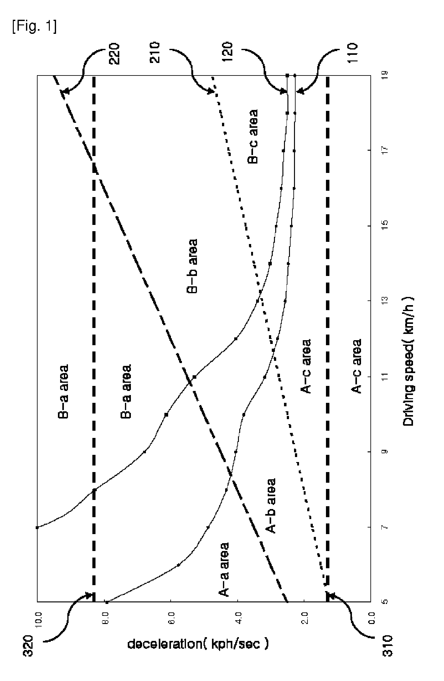
[0023]It is yet still another object of the present invention to resolve a problem in that, in a conventional treadmill, a motor driving portion does not endure an overload caused by quick deceleration.
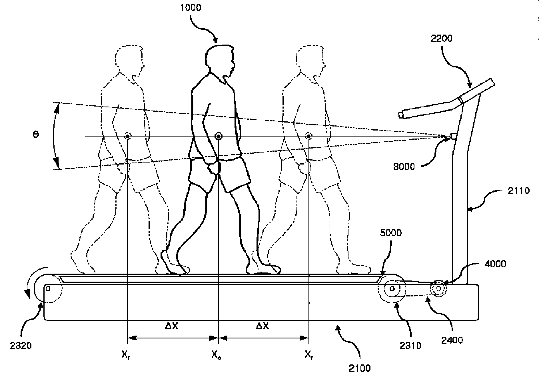
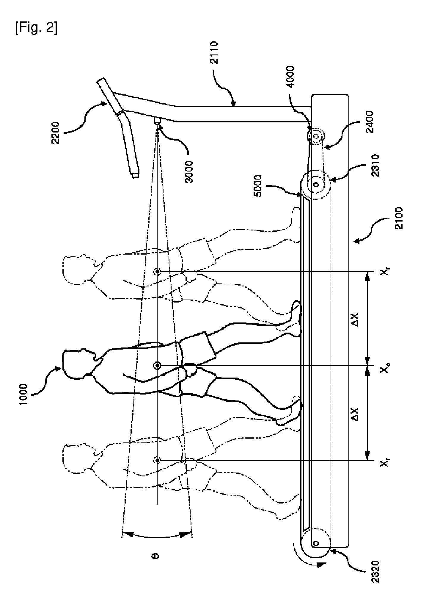
[0065]The treadmill according to the present invention pre-processes measured values of an exerciser's position and thus has an advantage of resolving a problem in that a speed of a belt can not be controlled due to measurement errors contained in measured values.

Problems solved by technology

Therefore, such a conventional treadmill does not provide a good exercising experience to an exerciser and is also difficult to realize a natural feeling that an exerciser can have while walking or running on the ground.
The treadmill disclosed in Korean Patent No. 10-0398330 performs acceleration or deceleration when a position of the exerciser is within a certain range from the central region, but the treadmill cannot handle various situations such as quick deceleration when an exerciser desires to abruptly stop while running at a high speed.
In addition, when a quick deceleration occurs, an overload occurs in a motor driving portion, and the motor driving portion stops driving the motor to protect itself.
Thus, a conventional treadmill cannot execute a quick deceleration.
Also, since an abrupt deceleration during exercise can cause an exerciser to fall due to inertia and potential injury risks, a conventional treadmill has implemented a slow deceleration or a deceleration using a natural friction force.
Further, such a conventional treadmill cannot effectively implement various exercising patterns of an exerciser.
In order to improve an overall exercise experience and to cope with various exercising patterns of an exerciser, a treadmill needs to rapidly follow acceleration and deceleration of an exerciser, but a conventional treadmill cannot perform quick deceleration and thus cannot provide a satisfactory automatic speed control function.
Therefore, it is difficult to implement an automatic speed control function using only a technique for measuring an exerciser's position by an ultrasonic sensor in a treadmill.
In addition, measured values received from an ultrasonic sensor can be distorted due to various ambient noise, and undesired measured values, for example, a position value of an arm or a leg, may be obtained while an exerciser walks or runs.
Such signal distortion and undesired measured values make it difficult for a treadmill to automatically control a speed of a belt.
However, the above-described techniques using load sensors have a problem in that a cycle of a load that is applied to a load sensor depends on a speed of an exerciser, and a cycle of a load of when an exerciser runs at a highest speed is 2 or 3 times per second.
This makes it very difficult to smoothly control the belt speed.
Thus, it is difficult to accurately calculate a position of an upper body of an exerciser or the center of gravity.
In addition, the above-mentioned Korean Patent Publications have not mentioned a control method for coping with various exercising patterns of an exerciser, such as quick acceleration or quick deceleration, and so it is difficult to automatically control the belt speed only using a difference between an exerciser's position and a reference position in a manner that provides satisfactory automatic speed control.

Method used


Image

  • Treadmill with automatic speed control, control module of the same and control method of the same
  • Treadmill with automatic speed control, control module of the same and control method of the same
  • Treadmill with automatic speed control, control module of the same and control method of the same

Examples


Embodiment Construction

[0080]While the invention is susceptible to various modifications and alternative forms, specific embodiments thereof are shown by way of example in the drawings and will herein be described in detail. However, it should be understood that there is no intent to limit the invention to the particular forms disclosed, but on the contrary, the invention is to cover all modifications, equivalents, and alternatives falling within the spirit and scope of the invention. In the drawings, like reference numerals denote like parts.

[0081]It will be understood that, although the terms first, second, etc. may be used herein to describe various elements, these elements should not be limited by these terms. These terms are only used to distinguish one element from another. For example, a first element could be termed a second element, and, similarly, a second element could be termed a first element, without departing from the scope of the present invention. As used herein, the term “and / or” include...


PUM


Abstract

The present invention provides a treadmill with an automatic speed control function, including: a body having a belt for supporting an exerciser; an exerciser detecting portion installed in a predetermined area of the body to detect movement of the exerciser; a driving motor coupled to the body to drive the belt; a control portion for generating a control signal for adjusting a rotation speed of the driving motor based on a signal received from the exerciser detecting portion; and a motor driving portion for adjusting the rotation speed of the driving motor according to the control signal received from the control portion, wherein a provision braking torque provided corresponding to the control signal is varied as the rotation speed of the driving motor is reduced. The treadmill quickly follows acceleration or deceleration of an exerciser, realizes a feeling like what an exerciser has while exercising on the ground to thereby improve an exerciser's exercising feeling, accepts various exercising patterns of an exerciser, resolves a problem in that a motor driving portion is tripped due to a load caused by quick deceleration, and pre-processes measured values of an exerciser's position to resolve a problem in that a speed of a belt can not be controlled due to measurement errors contained in measured values.

Description

CLAIM FOR PRIORITY[0001]This application claims priority to Korean Patent Application No. 10-2007-0104222 filed on Oct. 16, 2007, Korean Patent Application No. 10-2007-0129436 filed on Dec. 12, 2007, Korean Patent Application No. 10-2007-0129438 filed on Dec. 12, 2007, Korean Patent Application No. 10-2007-0129439 filed On Dec. 12, 2007, Korean Patent Application No. 10-0136452 filed on Dec. 24, 2007, Korean Patent Application No. 10-2007-0136453 filed on Dec. 24, 2007, Korean Patent Application No. 10-2007-0136455 filed on Dec. 24, 2007, Korean Patent Application No. 10-2007-0136456 filed on Dec. 24, 2007, Korean Patent Application No. 10-2007-0136457 filed on Dec. 24, 2007, Korean Patent Application No. 10-2007-0136458 filed on Dec. 24, 2007, Korean Patent Application No. 10-2007-0136459 filed on Dec. 24, 2007, Korean Patent Application No. 10-2007-0136460 filed on Dec. 24, 2007, and Korean Patent Application No. 10-2007-0136462 filed on Dec. 24, 2007 in the Korean Intellectual Pr...

Claims


Application Information

Patent Timeline
IPC IPC(8): A63B24/00A63B22/02
CPCA63B21/0053A63B2225/64A63B22/0056A63B22/0235A63B22/0605A63B22/0664A63B24/0087A63B2021/0055A63B2022/025A63B2022/067A63B2024/0096A63B2220/10A63B2220/13A63B2220/802A63B2220/805A63B2220/833A63B22/001A63B22/025A63B21/0055A63B21/0059A63B21/005A63B21/0058A63B22/0242A63B2024/0093A63B2220/40A63B2225/50H02P3/18A63B2071/0641A63B2220/34A63B22/02
Inventor PARK, JAE-SANG
Owner KAESUN SPORTS
Learn More