Method and apparatus for changing the trajectory of a projectile

a projectile and trajectory technology, applied in the field of defensive shielding, can solve the problems of increasing the weight of the vehicle, reducing the mobility of the vehicle, and changing the design of the armor, and achieve the effect of reducing the effectiveness of impacts

Inactive Publication Date: 2010-08-26
U S TECH ARMOR
View PDF23 Cites 13 Cited by
  • Summary
  • Abstract
  • Description
  • Claims
  • Application Information

AI Technical Summary

Benefits of technology

[0012]The present invention is a protrusion armor system which combines the best features of composite, spaced armor and sloping armor technologies, but also adds a new and novel approach to reducing the effectiveness of impacts. This new invention relies on deflection to affect the trajectory of a projectile such that it is diverted away from the optimum angle of attack. The deflection changes the impact point of the projectile from the projectile's tip, where all the mass-energy is concentrated into the smallest possible area, to a region on the projectile having a greater surface area such as the shoulder or side wall of the projectile.

Problems solved by technology

This increased the vehicle's weight, which in turn reduced its mobility.
This weight / mobility problem has led to changes in armor design.
Spaced armor reduces the penetrating power of bullets and solid shot.
After penetrating each plate, projectiles tend to tumble, deflect, deform, or disintegrate.
These planar, angled surfaces also increase the chance of deflecting a projectile, which happens when the bullet is traveling at a trajectory close to the slope of the planar surface.
The major drawback with this type of angle-armor technology is that at certain angles, the impact of some projectile hits will not be affected by sloping, such as a “direct hit” at a substantially perpendicular angle.
If the thickness is increased, the weight of the vehicle increases, therefore the costs involved increase.
If the thickness is not increased to a degree sufficient for impacts at these angles, personnel are left at a greater risk of injury.
This increases the probability that the previously known armor technologies will be less capable of stopping modern projectiles.

Method used


Image

  • Method and apparatus for changing the trajectory of a projectile
  • Method and apparatus for changing the trajectory of a projectile
  • Method and apparatus for changing the trajectory of a projectile

Examples


first embodiment

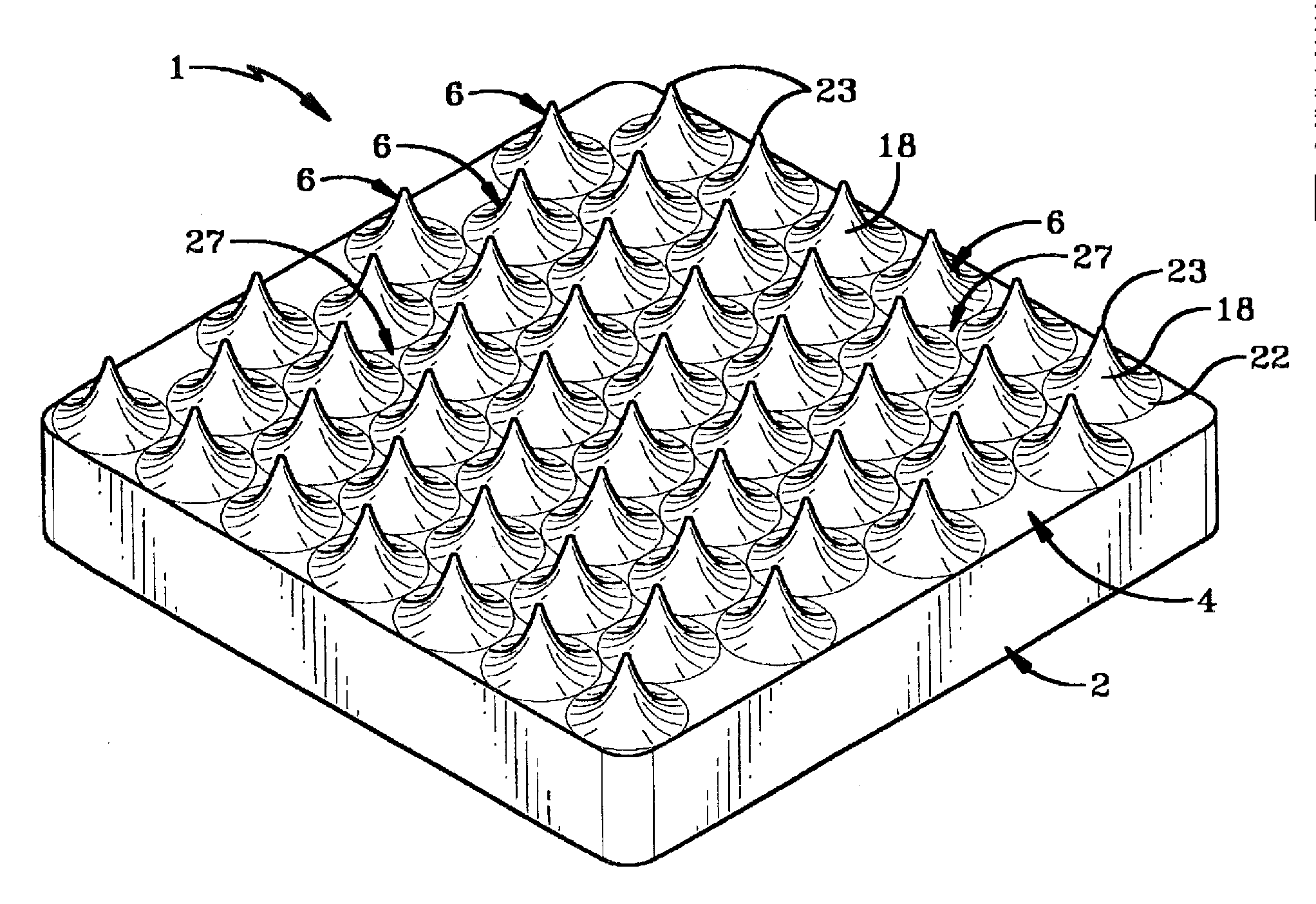
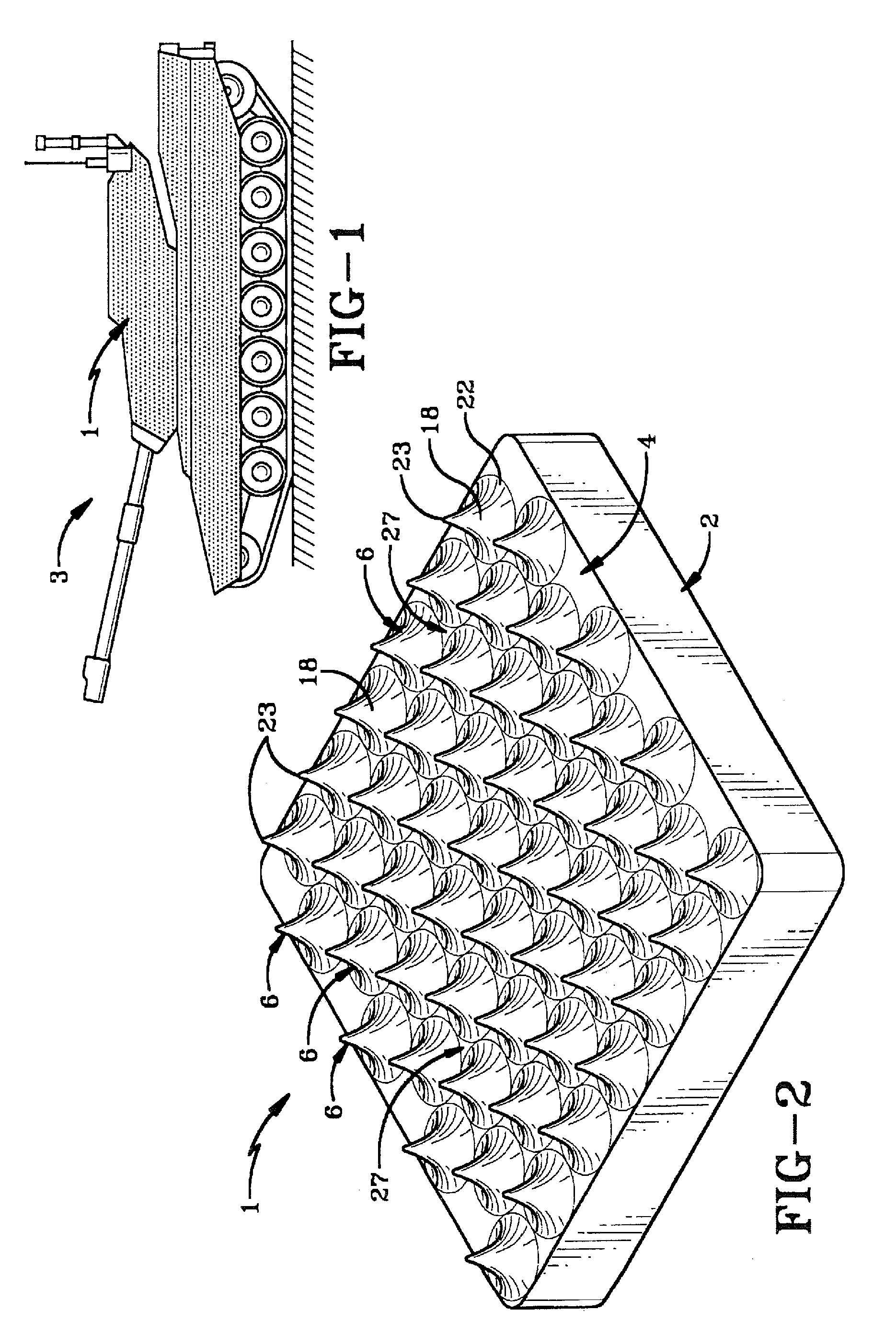
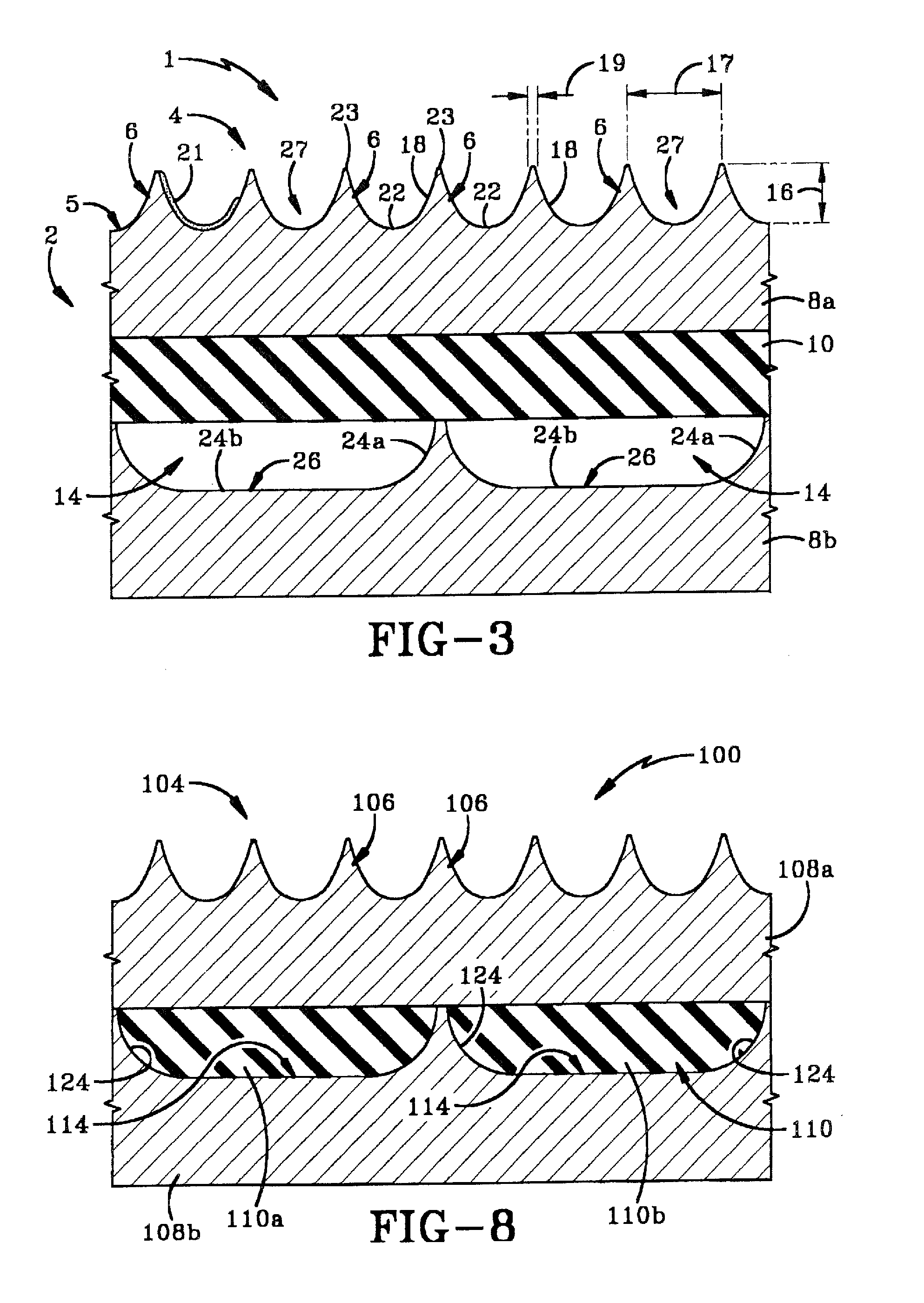
[0034]Referring to FIG. 3, there is shown armor 1 wherein the armor base 2 is a composite armor being made from at least two materials, such as steel and ceramic. The steel and ceramic are disposed in layers, such as in an exterior layer 8a, a middle layer 10 and an interior layer 8b. So, for example, in FIG. 3, exterior and interior layers 8a, 8b may be steel layers and middle layer 10 may be a ceramic layer. Layers 8a, 8b, and 10 are secured together in any manner known in the art. It will be understood that a plurality of layers of each of the two materials may be integrated into armor base 2. It will further be understood that additional layers of other materials, such as rubber or polymers, may also be incorporated therein.

[0035]Armor base 2 preferably further defines one or more caverns 14 spaced a distance inwardly from armor face 4. Caverns 14 are shown defined in interior layer 8b, but may alternatively or additionally be formed in any of the other layers. Each cavern 14 co...

second embodiment

[0044]protrusion armor system is shown in FIG. 8 and generally indicated at 100. Armor 100 comprises a first layer 108a and a second layer 108b made from the same material. A second material 110 is provided in discrete pockets 110a and 110b within material 108. Armor 100 includes protrusions 106 that provide a similar type of protection as armor 1, but in addition to this pockets 110a and 110b include arcuate interior sidewalls 124. These arcuate sidewalls 124 aid in deflecting projectiles 30 in much the same way as the sidewalls 118 of protrusions 106, except that a projectile would be forced to travel through the material within pocket 110a and 110b whereby the kinetic energy of the projectile will therefore be greatly dissipated.

[0045]Operationally, the second embodiment of the present invention deflects projectiles in the same method as the first embodiment. The second embodiment of protrusion armor system 110 deflects projectiles using a plurality of a protrusion 106 on an armo...


PUM


Abstract

An armor system comprising an armor base, an armor face on the armor base positioned as to be the first impact point of an incoming projectile, and a plurality of protrusions that extend outwardly away from the armor face. The protrusions act to affect the trajectory of an incoming projectile and divert it away from the optimum angle of attack.

Description

BACKGROUND OF THE INVENTION[0001]1. Technical Field[0002]The invention relates to defensive shielding. More particularly, the invention relates to a defeat mechanism for projectile rounds. Specifically, the invention provides a deflection mechanism to affect the trajectory of a projectile such that it is diverted away from an optimum angle of attack.[0003]2. Background Information[0004]Known defeat mechanisms (armor) for projectile rounds (bullets) have traditionally relied on hardness, tackiness, elongation, weave or other material characteristics for energy absorption. Military vehicles are armored to withstand the impact of shrapnel, bullets, missiles, or shells, protecting the personnel inside from enemy fire. Such vehicles include tanks, aircraft, and ships.[0005]Through the end of World War II, the type of armor used on almost all tanks and other armored vehicles was a sheet of steel. Increasing the protection on a vehicle meant adding thicker steel sheets. This increased the ...

Claims


Application Information

Patent Timeline
Patent Type & Authority Applications(United States)
IPC IPC(8): F41H5/007F41H5/04F41H7/04
CPCF41H7/04F41H5/0421
Inventor WILLIAMS, RAYMOND F.EISENHUT, JOHN D.
Owner U S TECH ARMOR
Why Eureka
Try Eureka