Hydro-Pneumatic Cylinder with Controlled Stop Position

Inactive Publication Date: 2010-08-26
NITROGAS
View PDF4 Cites 0 Cited by
  • Summary
  • Abstract
  • Description
  • Claims
  • Application Information

AI Technical Summary

Benefits of technology

[0008]The cylinder also comprises closure means linked to the body base and designed to close the flow duct when the rod reaches the stop position, thereby preventing the communication between the main chamber and the auxiliary chamber, and, therefore, preventing the passage of fluid from one chamber to the other. When the flow duct is closed, said closure means also cause an increase in the volume of the main chamber, causing the fluid present in said main chamber to expand.
[0010]The compression property of an oily fluid is lower than that of a gaseous fluid, which means that when the volume of the main chamber increases when the rod is in the stop position, and the oily fluid present in said main chamber expands, the pressure of said oily fluid is lower than that of the gaseous fluid of the auxiliary chamber, thereby preventing any movement of the rod to the rest position that may cause damage to a piece, when the flow duct is closed, the stopping of the rod of the cylinder being controlled. Thus, the stopping of said rod may be controlled without the need to add an external accumulator to the cylinder of the invention, thus making the cylinder easier to install.

Problems solved by technology

This may cause serious problems in the piece obtained during the material forming process, with the possibility that it may be deformed if the rod hits it when it is returning to its original position, for example.
When installing said gas cylinder sufficient space must be left in order to dispose the body of the cylinder, the accumulator, the electric valves and the ducts, something that is often complicated and which also makes said installation complex.

Method used


Image

  • Hydro-Pneumatic Cylinder with Controlled Stop Position
  • Hydro-Pneumatic Cylinder with Controlled Stop Position
  • Hydro-Pneumatic Cylinder with Controlled Stop Position

Examples


Embodiment Construction

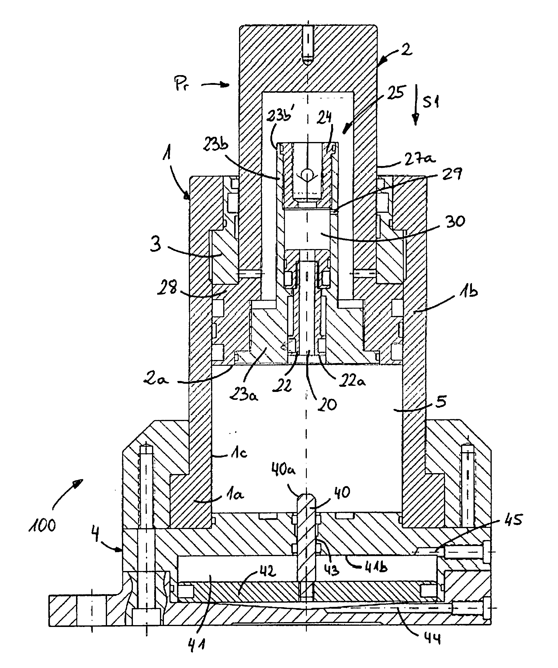
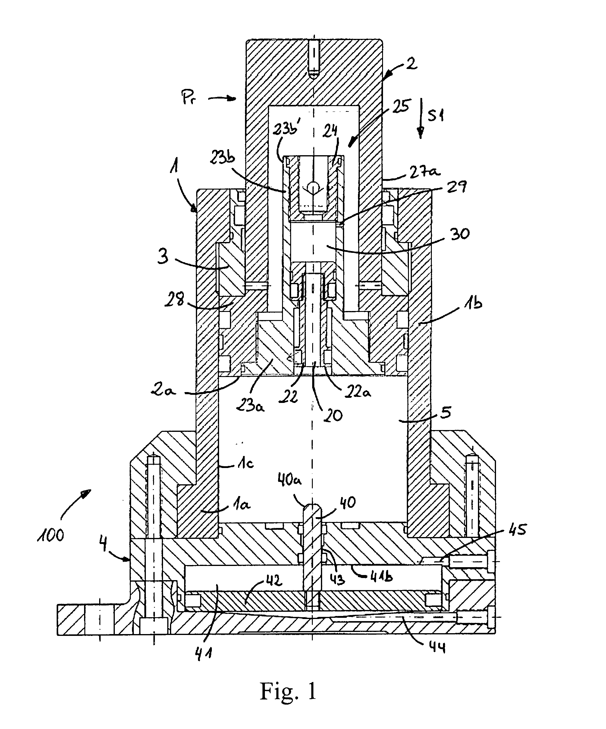
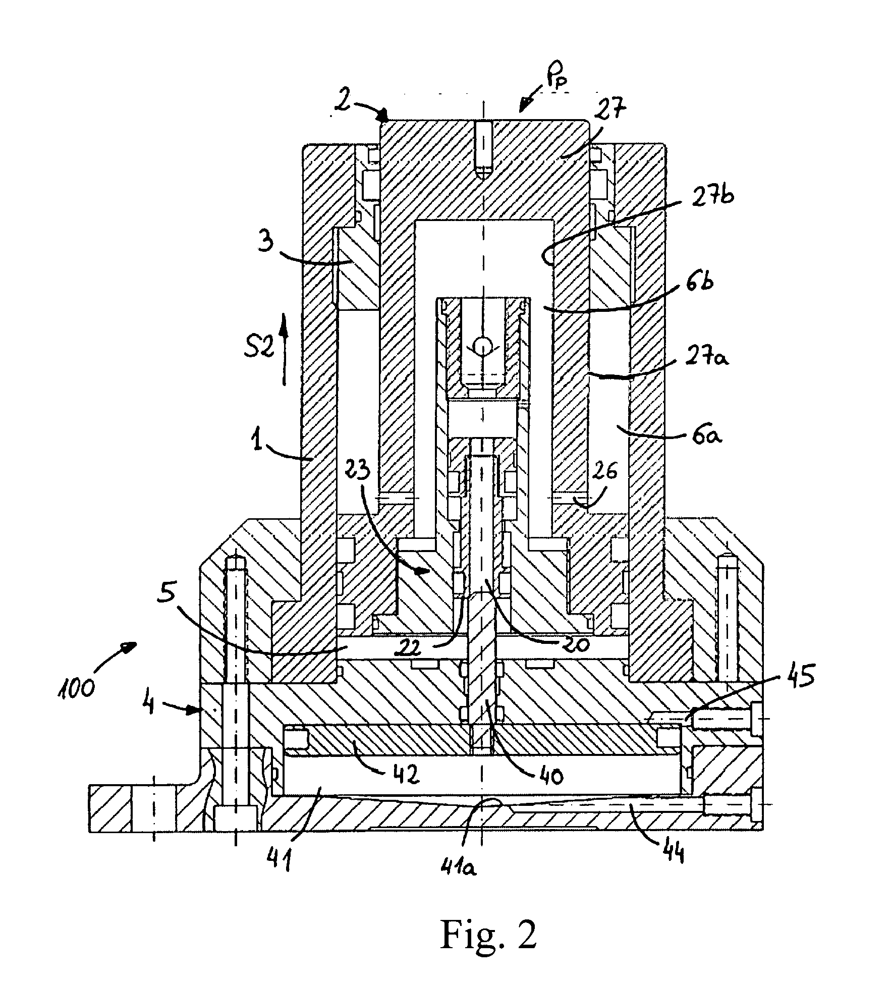
[0014]FIGS. 1 and 2 show an embodiment of the gas cylinder 100 of the invention. The cylinder 100 comprises a hollow cylinder body 1, preferably cylindrical, a body base 4 fixed to a first end 1a of the cylinder body 1, although it may also form part of said cylinder body 1, and a rod 2 that is axially movable inside the cylinder body 1 from a rest position Pr shown in FIG. 1 to a stop position Pp shown in FIG. 2, towards the body base 4 in a stop direction S1, or from the stop position Pp to the rest position Pr in a release direction S2, and which comprises an axial rod body 27 and a ring-shaped rod base 28 fixed to one end of said rod body 27. The cylinder 100 also comprises a main chamber 5 inside the cylinder body 1, which comprises at least one pressurised fluid in its interior when said rod 2 is in the rest position Pr, an auxiliary chamber 6a, 6b independent to the main chamber 5, and a flow duct 20 that is disposed inside the rod 2 and which communicates the main chamber 5 ...


PUM


Abstract

A cylinder having a hollow cylindrical body with an axially moveable rod disposed therein that is moveable between a rest position and a stop position. The cylindrical body and rod are configured so as to create a main chamber located between a lower surface of the rod and a base of the cylindrical body. And to also create an auxiliary chamber that is connectable to the main chamber via a flow channel in the rod. In one implementation the main chamber is adapted to contain a gaseous fluid and an oily fluid mixture when the rod is in the rest position so that the fluid exerts a first force on the lower surface of the rod to urge the rod toward the rest position. When the rod is in the stop position the main chamber predominately contains only the oily fluid. The auxiliary chamber is in flow communication with the main chamber via the flow channel when the rod is not in the stop position, the first auxiliary chamber, main chamber and flow channel configured to cause at least the gaseous fluid to be located in the main chamber to pass through the flow channel to the auxiliary chamber when the rod is moved in a direction towards the stop position so that at least the gaseous fluid exerts a second force on a surface of the rod, opposite the lower surface of the rod, that acts against the first force. A closure element coupled to a portion of the body base is also provided and adapted to close the flow channel in the rod when the rod is in the stop position.

Description

TECHNICAL FIELD[0001]The present invention relates to gas cylinders, generally used in forming material and of the controlled-stop type, so that the movement of a rod of said cylinders to its original position may be controlled without it affecting the piece being produced.PRIOR ART[0002]Gas cylinders comprise a cylinder body and a rod that moves axially inside said body when a force or pressure is exerted on it, for example, during a material forming process in which a piece is obtained by means of at least one blow. An upper die or punch, for example, may strike against a lower die or mould, underneath which are disposed the gas cylinders, the rod of which is displaced when said lower die suffers the blow exerted by the upper die.[0003]Gas cylinders also comprise a gas chamber, said gas being compressed when the rod moves as a result of the effect of the pressure exerted on it, or said gas being decompressed when said pressure is no longer exerted and the rod returns to its origin...

Claims


Application Information

Patent Timeline
IPC IPC(8): F15B15/26
CPCF16F9/061F16F9/49F16F9/48B21D24/02B30B15/02F16F9/06
Inventor VALOR VALOR, ANTONIOGABICAGOGEASCOA BENITO, ALBERTO
Owner NITROGAS
Why Eureka
Try Eureka