Multi-Layered Color-Enhancing Nail Applique

a nail applique and multi-layer technology, applied in the field of nail appliques, can solve problems such as inability to create, and achieve the effect of bright and/or textured looks

Active Publication Date: 2010-08-26
PARK FA YOUNG
View PDF71 Cites 17 Cited by
  • Summary
  • Abstract
  • Description
  • Claims
  • Application Information

AI Technical Summary

Benefits of technology

[0008]In another embodiment, the bottom and top layers combine to produce a complementary visual effect In this embodiment, the bottom layer functions to hide the color of a natural nail, but it also visually combines with the layer on top to produce a unique appearance. In one example, the bottom layer is a coating having a metallic sheen (“metallic layer”) and a colored, translucent layer is applied on top of the metallic layer The metallic layer obscures the color of the underlying nail, but it also is visible through the translucent layer disposed on top thereof. The combined effect of the metallic and top, translucent layers produce a unique bright and / or textured look that is not possible to create with prior art methods.

Problems solved by technology

The combined effect of the metallic and top, translucent layers produce a unique bright and / or textured look that is not possible to create with prior art methods.

Method used


Image

  • Multi-Layered Color-Enhancing Nail Applique
  • Multi-Layered Color-Enhancing Nail Applique
  • Multi-Layered Color-Enhancing Nail Applique

Examples


Embodiment Construction

[0019]The following is a detailed description of the preferred embodiments of the invention, reference being made to the drawings in which the same reference numerals identify the same elements of structure in each of the several figures. It should be noted that these drawings are merely exemplary in nature and in no way serve to limit the scope of the invention, which is defined by the claims appearing herein below.

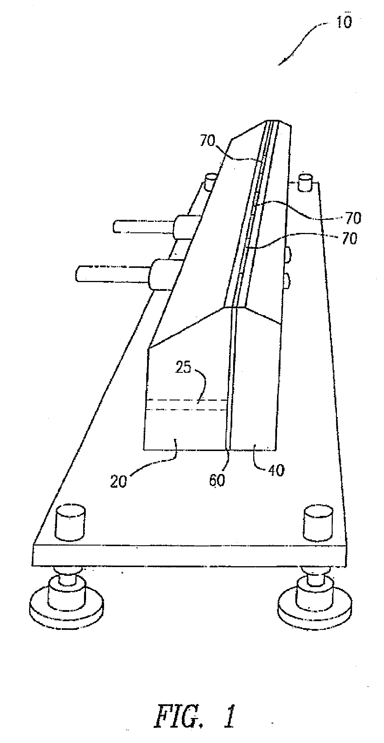
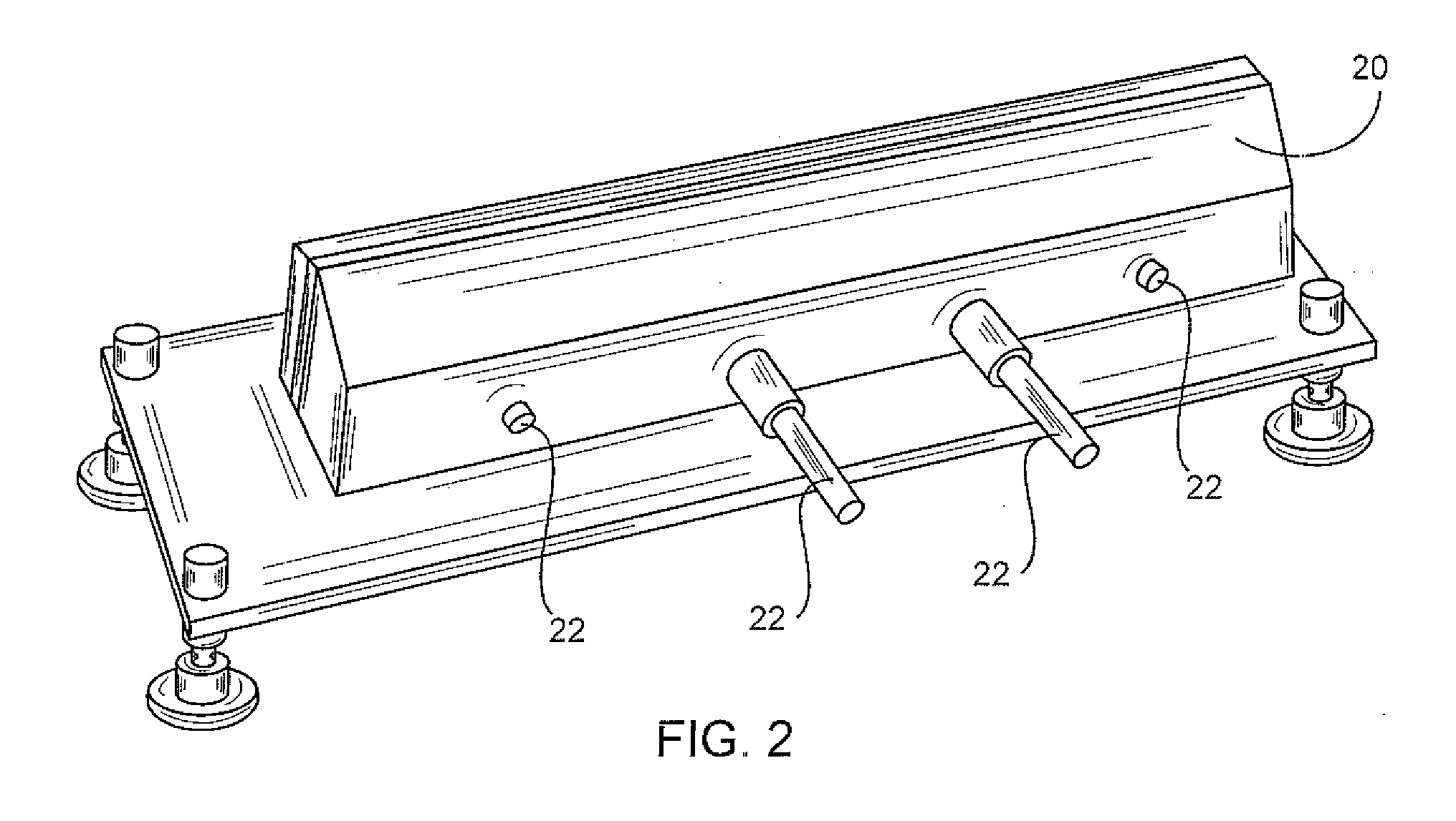
[0020]The various coatings of the product are applied via a technique referred to herein as “slot curtain die coating.” The die in question is shown in FIGS. 1-4 in various states of assembly as die 10. As best shown in FIG. 1, die 10 includes front die section 20, rear die section 40, and a specially shaped shim 60 disposed therebetween. All three parts are tightly secured together, preferably by bolting, e.g., by bolts 24 (see FIG. 6). Referring to FIG. 2, front die section 20 includes inlets 22 which feed internal bores 25 with liquid nail enamel or any of the other c...


PUM


Abstract

A thy nail polish appliqué to be applied to a fingernail. The nail appliqué has several layers. A bottom layer hides the color of the natural nail upon which the appliqué is applied. A top layer of a different color is applied on top of the color-hiding layer. The color of the top layer is, as such, uninfluenced by the natural nail color and it therefore appears sharp and crisp. The top layer could be of a translucent quality such that the top layer and bottom layer visually combine to produce a unique appearance

Description

RELATED APPLICATIONS[0001]The current application is a Continuation-In-Part of pending U.S. patent application Ser. No. 12 / 615,410, filed Nov. 10, 2009, which is a Continuation-In-Part of pending U.S. patent application Ser. No. 12 / 183,385 filed on Jul. 31, 2008, which itself is a Continuation-In-Part of pending U.S. patent application Ser. No. 12 / 138,701 filed on Jun. 13, 2008, which is a Continuation-In-Part of pending U.S. patent application Ser. No. 11 / 866,678 filed on Oct. 3, 2007, which is a Continuation-In-Part of pending U.S. patent application Ser. No. 11 / 543,481 filed Oct. 5, 2006, which is itself a Continuation-In-Part of U.S. patent application Ser. No. 11 / 126,862, filed on May 11, 2005, which claims domestic priority from U.S. Provisional Patent Application No. 60 / 570,713, filed on May 12, 2004. The contents of each of the above-mentioned patent applications are incorporated by reference herein.FIELD OF THE INVENTION[0002]The current invention relates generally to the f...

Claims


Application Information

Patent Timeline
Patent Type & Authority Applications(United States)
IPC IPC(8): A45D29/00
CPCA45D29/001
Inventor PARK, FA YOUNG
Owner PARK FA YOUNG
Why Eureka
Try Eureka