Stormwater plug flow separation system

a plug flow and stormwater technology, applied in the direction of sedimentation settling tanks, separation processes, liquid displacement, etc., can solve the problems of poor plug flow control and undesirable turbulen

Active Publication Date: 2010-08-26
NEWTERRA CORP INC
View PDF10 Cites 16 Cited by
  • Summary
  • Abstract
  • Description
  • Claims
  • Application Information

AI Technical Summary

Problems solved by technology

A prior STORMGATE SEPARATOR™ system used a circularly cross-sectioned transfer opening between an inlet chamber and

Method used


Image

  • Stormwater plug flow separation system
  • Stormwater plug flow separation system
  • Stormwater plug flow separation system

Examples


Embodiment Construction

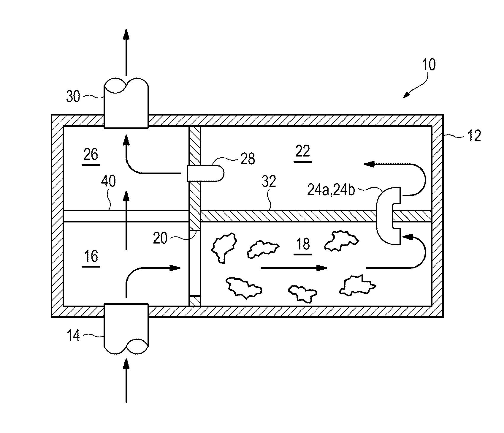
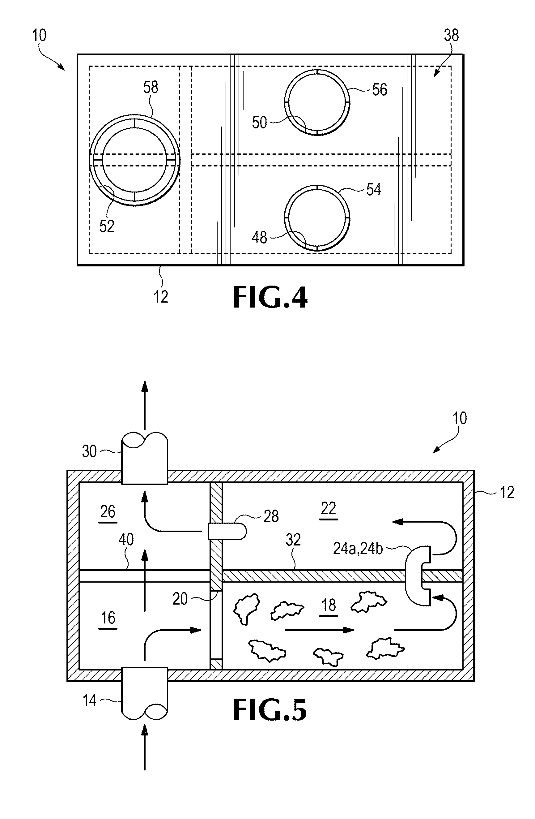
[0008]FIGS. 1-3 collectively illustrate the water plug flow separation system 10 in accordance with one embodiment of the invention. System 10 includes a stormwater flow container generally indicated at 12. Container 12 in turn includes (generally in the downstream direction of progressive stormwater flow separation) a water inlet pipe 14 or equivalent structure; an inlet chamber 16 in fluid communication with water inlet pipe 14; a first settling chamber 18 in fluid communication with inlet chamber 16 and configured to settle coarser solids and to float floatables; an elevated, horizontally-oriented, elongate-rectangular water treatment flow inlet 20 leading from inlet chamber 16 to first settling chamber 18; a second settling chamber 22 configured to settle finer solids; one or more (e.g. two) plug flow conduits 24a and 24b leading from first settling chamber 18 to second settling chamber 22; an outlet chamber 26 in fluid communication with second settling chamber 22; an elevated ...


PUM

PropertyMeasurementUnit
Flow rateaaaaaaaaaa
Shapeaaaaaaaaaa
Widthaaaaaaaaaa

Abstract

A water separation system includes a flow container includes a water inlet pipe; an inlet chamber in fluid communication with the water inlet pipe; a first settling chamber configured to settle grit and to float oil; an elevated, horizontally-oriented, elongate-rectangular water treatment flow inlet leading from the inlet chamber to the first settling chamber; a second settling chamber configured to settle solids; one or more plug flow conduits leading from the first settling chamber to the second settling chamber; an outlet chamber; an elevated treatment flow outlet disposed between the second settling chamber and the outlet chamber; a water outlet pipe in fluid communication with the outlet chamber; and an overflow mechanism disposed between the inlet chamber and the outlet chamber.

Description

FIELD OF THE INVENTION[0001]The invention relates generally to the field of water flow management and treatment. More particularly, the invention relates to particulate separation or sequestration within a continuous water flow.BACKGROUND OF THE INVENTION[0002]Plug flow separation water management systems are known to provide for settling of grit and heavy particulate and to float oil and floatable particulate by providing one or more plug flow conduits between adjacent settling chambers within an in-line flow container. A prior STORMGATE SEPARATOR™ system used a circularly cross-sectioned transfer opening between an inlet chamber and a first settling chamber, that caused undesirable turbulence and poor plug flow control of water through the system. That system also featured a rectangular flow duct frame between the first and a second settling chamber. Flow of water through a second circular transfer opening between the second settling chamber and an outlet chamber was controlled by...

Claims


Application Information

Patent Timeline
IPC IPC(8): B01D21/02C02F1/00
CPCB01D21/0006B01D21/003B01D21/0042B01D21/2433E03F5/14C02F1/40C02F2001/007C02F2103/001B01D2221/12
Inventor GENERES, AYNNOLING, CALVIN PAUL
Owner NEWTERRA CORP INC
Why Eureka
Try Eureka