Electric drive system for an automotive vehicle

a technology for electric drive systems and automobiles, applied in the direction of electronic commutators, dynamo-electric converter control, instruments, etc., can solve the problems of increasing the cost, size, and need for non-standard components of electric drive systems, creating false and unnecessary failure modes, and interlocking systems, etc., to achieve the effect of increasing the cost of electric drive systems

Active Publication Date: 2010-08-26
FORD GLOBAL TECH LLC
View PDF2 Cites 36 Cited by
  • Summary
  • Abstract
  • Description
  • Claims
  • Application Information

AI Technical Summary

Benefits of technology

[0012]An electric drive system in an automotive vehicle is provided. The electric drive system may include a drive system inverter, a three-phase synchronous motor, and a three-wire high-voltage cable extending between the drive system inverter and the motor. In addition, the electric drive system may include a pair of current sensors. The current sensors generate respective sensor signals indicating respective amounts of current flowing through the three-wire high-voltage cable. Also, the electric drive system may include a resolver. The resolver generates a resolver signal that has position information of the motor.

Problems solved by technology

However, the current sensors 9 increase the cost, size, and need for non-standardized components in the electric drive system 1.
Consequently, the interlock system 5 illustrated in FIG. 1 may create false and unnecessary failure modes.
Furthermore, the interlock system 5 increases the cost of the electric drive system 1 because non-standardized components are used.
Furthermore, the interlock system 5 uses the three high-bandwidth current sensors 9, which increases the cost of the interlock system 5.

Method used


Image

  • Electric drive system for an automotive vehicle
  • Electric drive system for an automotive vehicle
  • Electric drive system for an automotive vehicle

Examples


Embodiment Construction

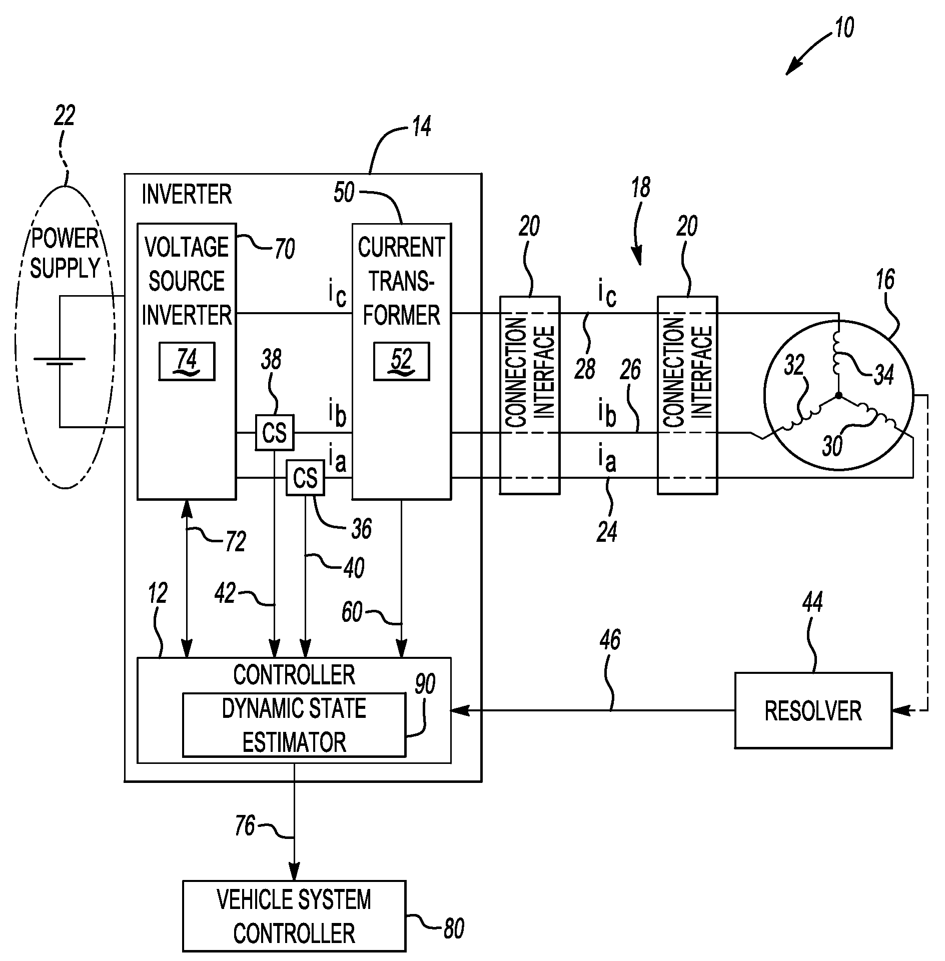
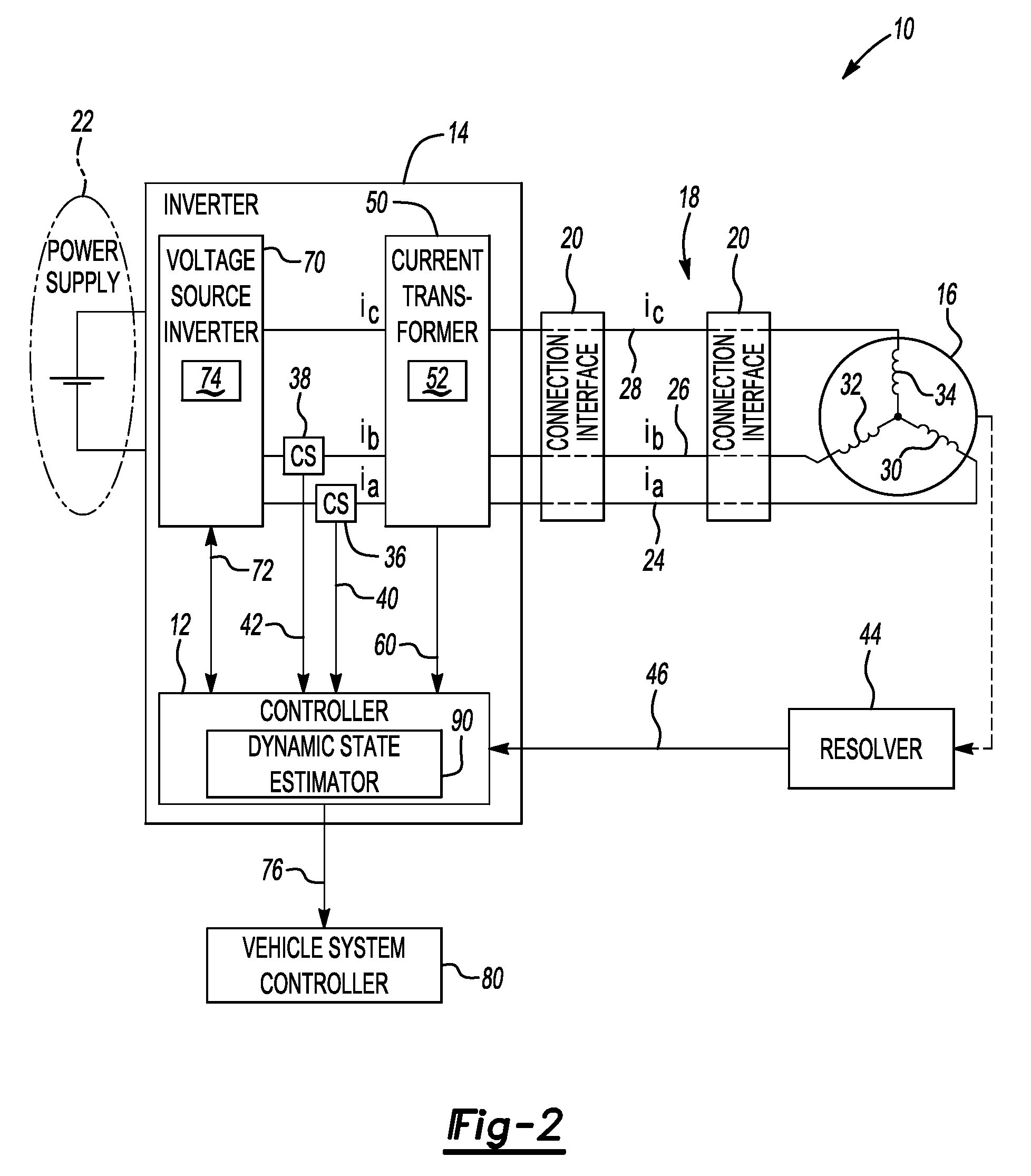
[0020]An embodiment of the present invention includes an electric drive system for an automotive vehicle. The electric drive system has a controller to determine a condition of the electric drive system based on one or more determinations. For example, the controller may determine an “interlocking condition” or a condition of an electrical connection between a drive system inverter and a motor in the electric drive system. Based on the interlocking condition, the controller can determine the condition of the electric drive system. Furthermore, the controller may calculate an amount of error between calculated currents and estimated currents to determine whether one or more problems exist in the electric drive system. In addition, the controller may control various operations of the electric drive system, which may or may not depend on the condition of the electric drive system.

[0021]FIG. 2 shows an electric drive system 10 for an automotive vehicle (not illustrated). The automotive ...


PUM


Abstract

An electric drive system in an automotive vehicle includes a controller for determining a condition of the electric drive system. The electric drive system includes only two current sensors and a common-mode current transformer. In response to the current sensors and the common-mode current transformer, the controller determines the condition of the electric drive system. The condition of the electric drive system may depend on a condition of an electrical connection between a drive system inverter and a motor in the electric drive system as well as a calculated amount of error in the electric drive system. In addition, the controller may control various operations of the electric drive system, which may or may not depend on the condition of the electric drive system.

Description

BACKGROUND[0001]1. Technical Field[0002]Electric drive system for an automotive vehicle.[0003]2. Background Art[0004]An electric drive system in an automotive vehicle typically includes a power electronics inverter and a permanent-magnet synchronous motor (PMSM). The inverter and the PMSM are typically spaced apart to reduce the total cost of the electric drive system and improve system package. Furthermore, the electric drive system may include an interlock system in an effort to increase the reliability and the safety of the electric drive system. The interlock system detects whether an electrical connection between the power electronics inverter and the PMSM is loose or disconnected. A three-wire high-voltage cable typically provides the electrical connection.[0005]FIG. 1 illustrates a prior art three-phase PMSM electric drive system 1 of an automotive vehicle having an inverter 2, a motor 3, a three-wire high-voltage cable 4 connecting the inverter 2 and the motor 3, an interloc...

Claims


Application Information

Patent Timeline
Patent Type & Authority Applications(United States)
IPC IPC(8): H02P6/18G01R31/58
CPCB60L3/0038B60L3/0069B60L11/1803G01R31/026Y02T10/7005H02P6/001H02P29/023Y02T10/642G01R31/343H02P29/0243H02P6/34B60L50/51G01R31/54Y02T10/64Y02T10/70G01R31/58
Inventor XIANG, JOSEPH YOUQING
Owner FORD GLOBAL TECH LLC
Why Eureka
Try Eureka