Display panel and display apparatus

a technology which is applied in the field of display panel and display device, can solve the problems of difficult to achieve such a configuration, difficult to design and produce such a device, and the appearance of the display region may be deteriorated, so as to achieve easy design and production, good appearance, and good appearance

Active Publication Date: 2010-08-26
SHARP KK
View PDF7 Cites 85 Cited by
  • Summary
  • Abstract
  • Description
  • Claims
  • Application Information

AI Technical Summary

Benefits of technology

[0008]The present invention has been made in view of the above-mentioned state of the art. The present invention has an object to provide an irregularly-shaped display panel which has a display region with a contour section having a good appearance and is easily designed and produced, and a display device.
[0009]The present inventors made various investigations on an irregularly-shaped display panel having a display region with a contour section having a good appearance, which is easily designed and produced. The inventors noted pixels constituting the contour section of the display region. Then, the inventors found the following. A Preferred embodiment may be employed, wherein a plurality of pixels located in a contour section of a display region include a pixel lacking at least one sub-pixel on a side of a frame region, and the contour section of the display region is defined by a plurality of the sub-pixels arranged stepwise by single sub-pixel units. Another Preferred embodiment may be employed, wherein a contour section of a display region is defined by a plurality of pixels arranged stepwise by single pixel units. Still another Preferred embodiment may be employed, wherein a plurality of pixels include pixels for a contour located in a contour section of a display region; sub-pixels constituting the pixel for a contour have aperture regions having similar aperture areas to one another and contour lines each running in parallel with a drawing direction of one of wirings at least on a side of a frame region; and the aperture area of the pixel for a contour is smaller than an aperture area of a pixel located at an inner side of the contour section of the display region. Further, the above Preferred embodiments may be employed in combination. An irregularly-shaped display panel with a contour section having a good appearance is easily designed and produced. As a result, the above-mentioned problems have been admirably solved, leading to completion of the present invention.
[0010]Namely, the present invention is a display panel comprising: a display region including an array of a plurality of pixels each constituted by a sub-pixel; and a frame region provided around the display region, wherein a plurality of pixels located in a contour section of the display region include a pixel lacking at least one sub-pixel on a side of the frame region, and the contour section of the display region is defined by a plurality of the sub-pixels arranged stepwise by single sub-pixel units (hereinafter, also referred to as a “first display panel of the present invention”). As a result, an irregularly-shaped display panel with a contour section having a good appearance is easily designed and produced.

Problems solved by technology

In the liquid crystal display device disclosed in Japanese Kokai Publication No. 2006-276580, the pixel on the boundary has an elliptical or circular aperture shape, and therefore, it is not easy at all to design and produce such a device.
Namely, it is very hard to achieve such a configuration.
If the aperture ratio of the pixel on the boundary is significantly adjusted in the configuration illustrated in FIG. 6 of Japanese Kokai Publication No. 2006-276580, namely, if the aperture ratio thereof is greatly different especially from the aperture ratio of a main pixel, the appearance of the display region may be deteriorated.
In addition, each pixel located on the boundary between the display region and the frame region does not always include all of the sub-pixels to be included in a pixel, and therefore, it is hard to adjust the aperture ratio of each pixel on the boundary.
Further, in the configurations illustrated in FIGS. 6 and 8 of Japanese Kokai Publication No. 2006-276580, the boundary of the display region tends to be rough especially in the case of a monochrome display, and the appearance of the display is deteriorated.

Method used


Image

  • Display panel and display apparatus
  • Display panel and display apparatus
  • Display panel and display apparatus

Examples


embodiment 1

Preferred Embodiment 1

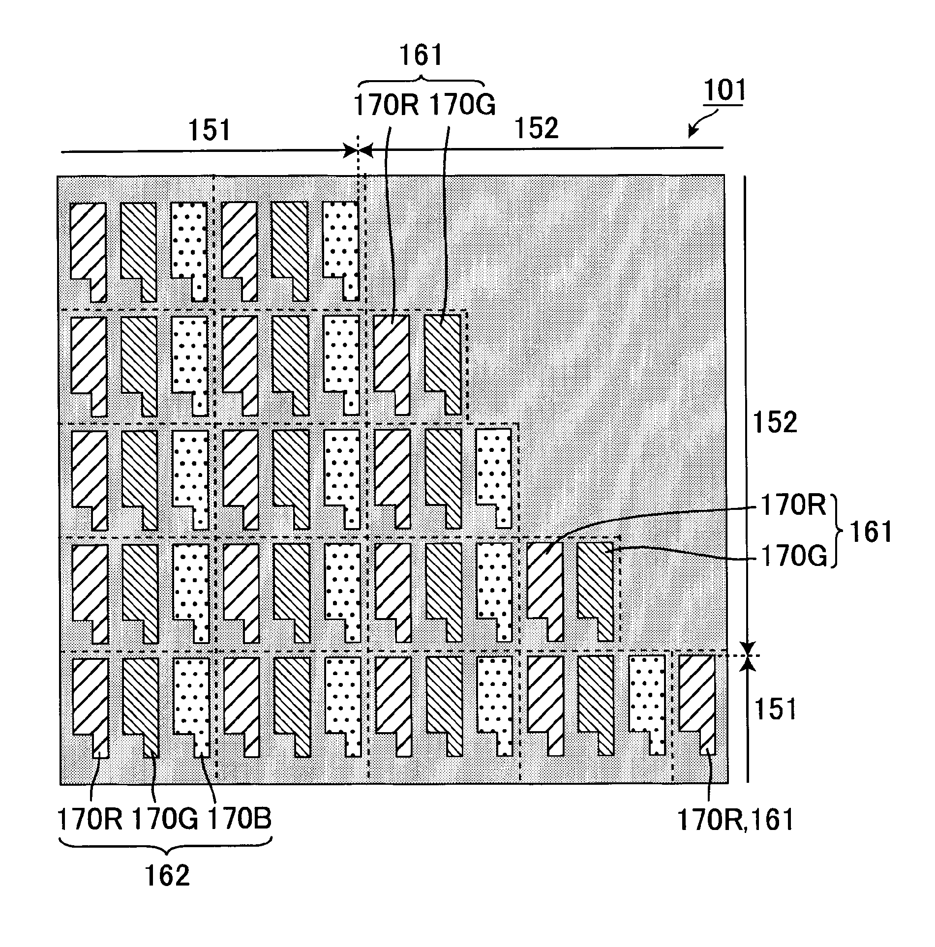
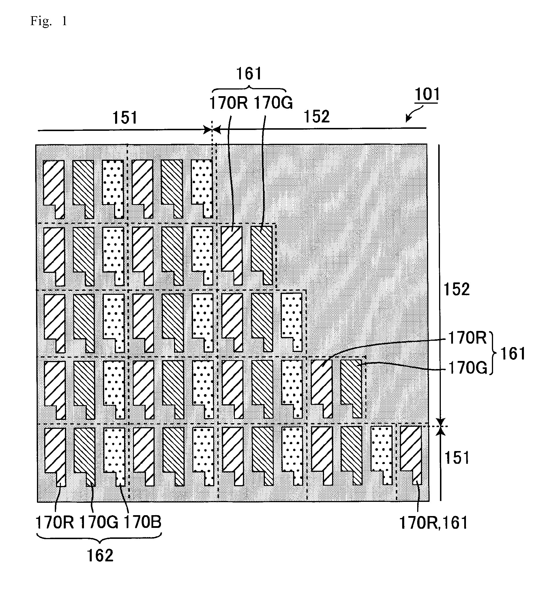
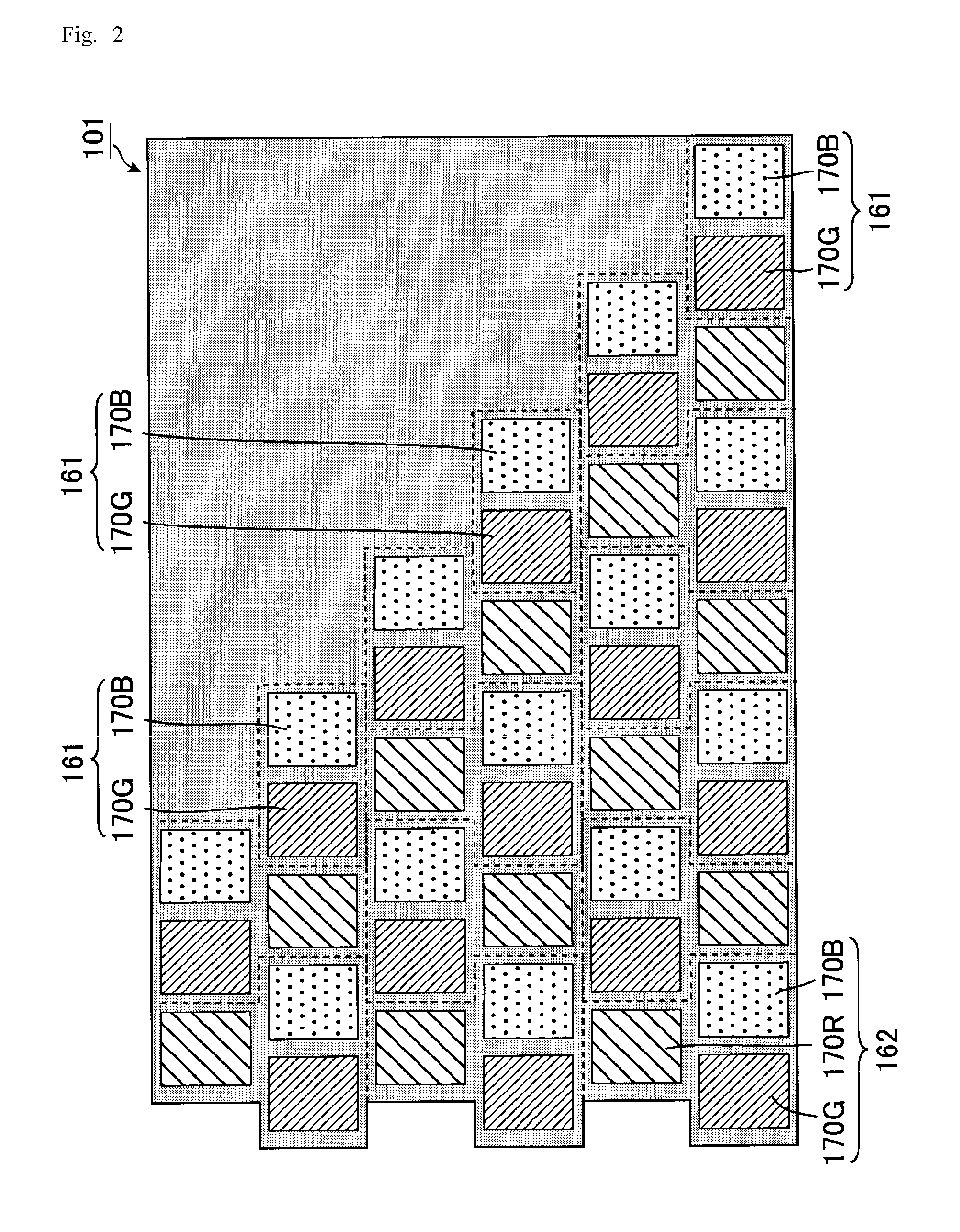
[0054]Preferred embodiment 1 of the present invention is mentioned with reference to FIGS. 1 and 2. FIG. 1 is a schematic plan view showing pixels in the vicinity of the frame section of the display region in the display panel of Preferred embodiment 1. FIG. 2 is a schematic plan view showing a variant example of the display panel of Preferred embodiment 1. It is to be noted that each of the regions defined by dotted lines in FIGS. 1 and 2 indicates a single pixel.

[0055]A display panel 101 of the present Preferred embodiment comprises, as shown in FIG. 1, a display region (display area) 151 in which a plurality of pixels are arranged in a matrix array, and a frame region (non-display area) 152 as a light-shielding region which displays nothing and is located around the display region 151. Each pixel is provided in the inner region of the display region 151 and includes a plurality of inner pixels 162 each constituted by a red (R) sub-pixel 170R, a green (G) sub...

embodiment 2

Preferred Embodiment 2

[0059]Preferred embodiment 2 of the present invention is mentioned with reference to FIGS. 3 and 4. FIG. 3 is a schematic plan view showing pixels in the vicinity of the contour section of the display region in the display panel of Preferred embodiment 2. FIG. 4 is a schematic plan view showing a variation of the display panel of Preferred embodiment 2. It is to be noted that, in the present Preferred embodiment, the same number is assigned to the member having the same function as in Preferred embodiment 1. Further, it is to be noted that the regions defined by dotted lines in FIGS. 3 and 4 each indicates a single pixel.

[0060]A display panel 102 of the present Preferred embodiment comprises, as shown in FIG. 3, a display region (display area) 151 in which a plurality of pixels 160 are arranged in a matrix array, and a frame region (non-display area) 152 as a light-shielding region which displays nothing and is located around the display region 151. Each pixel ...

embodiment 3

Preferred Embodiment 3

[0065]Preferred embodiment 3 of the present invention is mentioned with reference to FIGS. 5 to 11. FIG. 5 is a schematic plan view of the display panel of Preferred embodiment 3. FIG. 6 is a schematic cross-sectional view of the display panel of Preferred embodiment 3 and shows a cross section taken along line X-Y in FIG. 5. FIG. 7 is an enlarged schematic plan view showing a curved part of the display panel of Preferred embodiment 3 and shows the region indicated by dotted lines in FIG. 5. FIG. 8 is an enlarged schematic plan view showing the configuration of the curved part of the display panel of Preferred embodiment 3 and shows the same region indicated by the dotted lines in FIG. 5 as in FIG. 7. FIG. 9 is an enlarged schematic plan view indicating the configuration of the display panel of Preferred embodiment 3 shown in FIG. 8 on the side of an active matrix substrate. FIG. 10 is an enlarged schematic plan view showing the configuration of the display pan...


PUM


Abstract

The present invention provides an irregularly-shaped display panel having a display region with a contour section having a good appearance, which is easily designed and produced. The present invention is a display panel comprising a display region including: an array of a plurality of pixels each constituted by a plurality of sub-pixels; and a plurality of wirings provided along boundaries of the plurality of sub-pixels, wherein a plurality of pixels include a pixel for a contour located in a contour section of the display region; the sub-pixels constituting the pixel for a contour have aperture regions having similar aperture areas to one another and contour lines each running in parallel with a drawing direction of one of the wirings at least on the side of a frame region; and the aperture area of the pixel for a contour is smaller than an aperture area of a pixel located at an inner side of the contour section of the display region.

Description

BACKGROUND OF THE INVENTION[0001]1. Field of the Invention[0002]The present invention relates to a display panel and a display device. More specifically, the present invention relates to a display panel and a display device, suitably used in an irregularly-shaped display panel such as an in-car instrumental panel, a car navigation system, a display device for amusement equipment.[0003]2. Description of the Related Art[0004]A display device provided with a thinner display panel has been widely spread as a display device used in a TV, a personal computer, and a mobile phone. A liquid crystal display panel, a plasma display panel (hereinafter, also referred to as a “PDP”) and the like may be mentioned as a display panel in current practical use. Further, a panel for an organic electroluminescence device (hereinafter, also referred to as an “organic EL display”) may be mentioned as a display panel actively studied with an aim of the future diffusion thereof.[0005]Although various displa...

Claims


Application Information

Patent Timeline
Patent Type & Authority Applications(United States)
IPC IPC(8): G09G3/20
CPCG02F2201/52G02F1/136286G02F2201/56
Inventor OGASAWARA, ISAOFUJIHARA, TOSHIAKIYAMADA, TAKAHARU
Owner SHARP KK
Why Eureka
Try Eureka