
Methods and systems relating to overcurrent circuit protection

a technology of circuit protection and overcurrent, applied in emergency protective arrangements for limiting excess voltage/current, instruments, lighting and heating apparatus, etc., can solve problems such as time delay, limitation of current, and substantial reduction of current through ptc overcurrent protection devices

Active Publication Date: 2010-08-26
WOW DOOR CORP
View PDF45 Cites 77 Cited by
  • Summary
  • Abstract
  • Description
  • Claims
  • Application Information

AI Technical Summary

Benefits of technology

[0007]In another embodiment of the present invention, a method of providing overcurrent circuit protection is provided. The method may include defining a threshold current value according to an operational state of a mo...

Problems solved by technology

However, if the current through the PTC overcurrent protection device increases excessively, the ambient temperature around the PTC overcurrent protection device increases excessively, and / or the normal operating current is maintained for more than the normal operating time, the PTC overcurrent protection device will be “tripped,” and converted to a high temperature, high resistance state such that the current through the PTC overcurrent protection device is substantially reduced.
Because overcurrent protection utilizing a PTC device involves a thermal process, an unacceptable time delay occurring between application of an unsafe current (i.e., a current above a threshold value) and the limitation of the current may exist.
As such, circuit components may be susceptible to unsafe currents and, as a result, may be damaged.
Furthermore, once a PTC device is “tripped,” user interaction may be required to reset the device.

Method used


Image

  • Methods and systems relating to overcurrent circuit protection
  • Methods and systems relating to overcurrent circuit protection
  • Methods and systems relating to overcurrent circuit protection

Examples


Embodiment Construction

[0017]In the following description, circuits may be shown in block diagram form in order not to obscure the present invention in unnecessary detail. Conversely, specific circuit implementations shown and described are examples only and should not be construed as the only way to implement the present invention unless specified otherwise herein. Additionally, block definitions and partitioning of logic between various blocks is exemplary of a specific implementation. It will be appreciated by those of ordinary skill in the art that the present invention may be practiced by numerous other partitioning solutions. For the most part, details concerning timing considerations, and the like, have been omitted inasmuch as such details are not necessary to obtain a complete understanding of the present invention and are within the ability of persons of ordinary skill in the relevant art.

[0018]The terms “assert” and “negate” are respectively used when referring to the rendering of a signal, sta...


PUM


Abstract

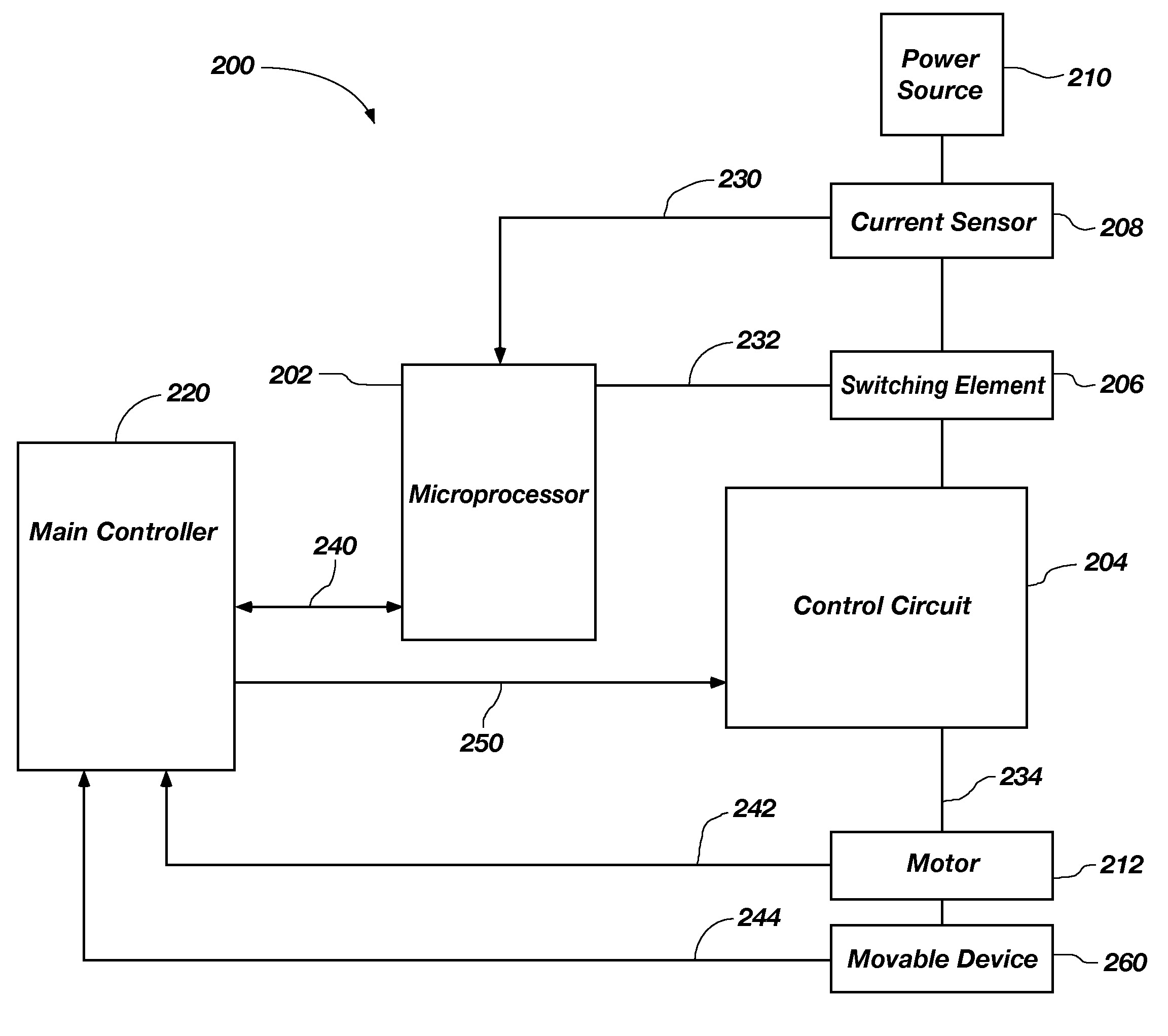
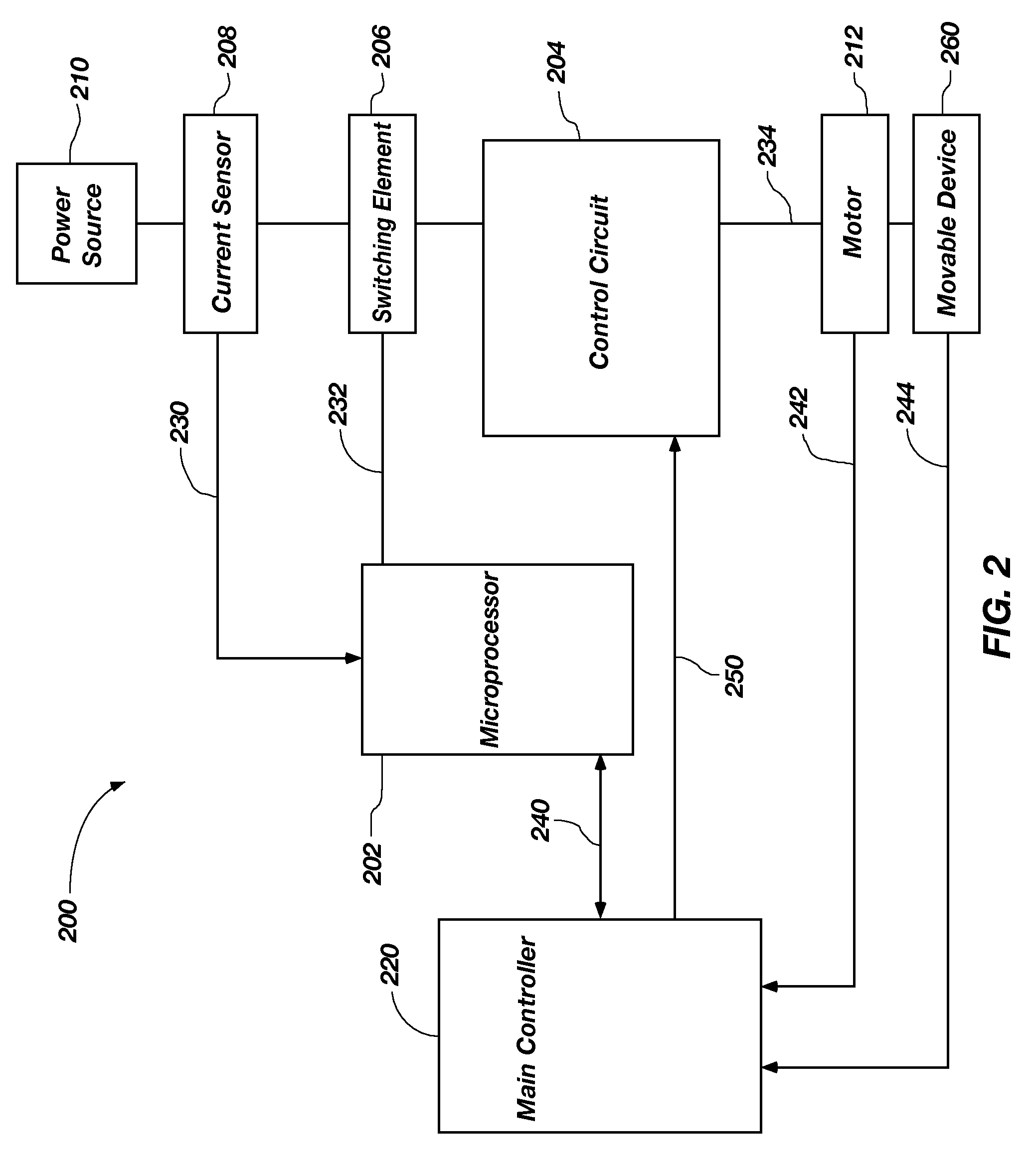
Systems and methods for providing overcurrent circuit protection are disclosed. A method of providing overcurrent circuit protection may include setting a threshold current value according to an operational state of a motor and sensing an amount of current being supplied to the motor. The method may further include electrically isolating the motor from a current source if the sensed current amount is greater than the threshold current value.

Description

TECHNICAL FIELD[0001]Embodiments of the present invention relate generally to overcurrent circuit protection and, more specifically, to systems and methods for providing microprocessor-based, variable threshold level overcurrent circuit protection.BACKGROUND[0002]Control circuitry for an electrical load, such as a motor, generally includes a protection device, such as a fuse, for deactivating the motor based on various operating conditions and the loading on the electric motor. Generally, a protection device is configured to interrupt the current to the motor when the current exceeds a predetermined threshold.[0003]As understood by one of ordinary skill in the art, positive temperature coefficient (PTC) materials are commonly used to protect an electrical circuit from overcurrent conditions. Such materials exhibit an electrical resistivity that is relatively low at a design operating temperature band and increases abruptly, as the temperature of the material rises beyond a critical ...

Claims


Application Information

Patent Timeline
IPC IPC(8): H02H9/08H02K17/32
CPCH02H7/0816H02H3/006
Inventor HALL, DUANE O.FIELD, D. GEORGEGOODMAN, E. CARLBANTA, KEVIN D.
Owner WOW DOOR CORP
Learn More