

Fireproof light fixture
- Summary
- Abstract
- Description
- Claims
- Application Information
AI Technical Summary
Benefits of technology
Problems solved by technology
Method used
Image

Examples
Embodiment Construction
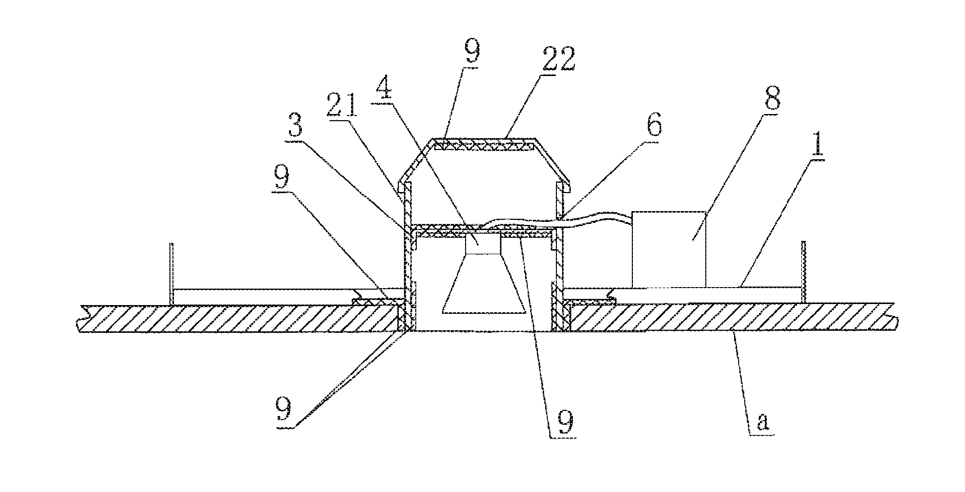
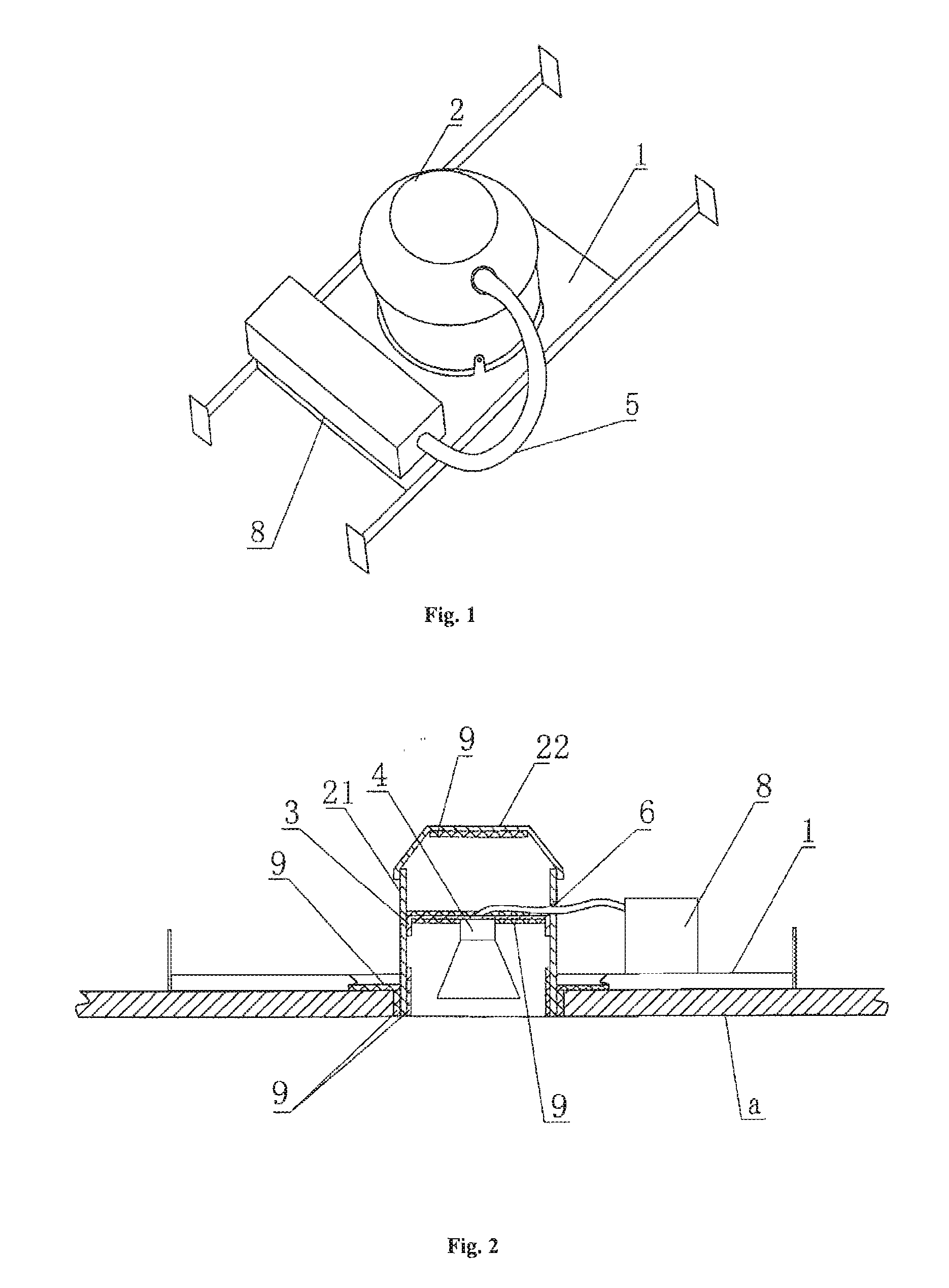
[0019]Referring to FIGS. 1 and 2, a fireproof light fixture comprises a supporting plate 1 and a mantle 2 mounted on the supporting pate 1. A bracket 3 is mounted inside the mantle 2, and a lamp holder 4 is fixed below the bracket 3. The mantle 2 is provided with a through hole 6, a pipe extends through the through hole 6. Electrical wires extending through the pipe 5 are connected between the lamp holder 4 and a junction box 8 outside of the mantle 2. A dilatable fireproof piece 9 mounted in the mantle 2.
[0020]Referring to FIG. 2, the dilatable fireproof piece 9 is fixed on the inner surface of the mantle 2 and the surface of the bracket 3. The “a” represents the ceiling; the light source is mounted on the lamp holder 4. When on fire, the dilatable fireproof piece 9 dilates to form a thick piece of carbide which then covers on the bracket 3 or the mantle 2 to realize the fire resistance and heat insulation, the temperature outside the light fitting will not be too high, and fire wi...
PUM
 Abstract
Description
Claims
Application Information