Battery pack and battery pack manufacturing method

a battery pack and manufacturing method technology, applied in the field of batteries, can solve problems such as the complexity of structure, and achieve the effect of simple structure and reliable mechanical strength of exterior parts

Inactive Publication Date: 2010-08-26
HITACHI MAXELL ENERGY LTD
View PDF1 Cites 6 Cited by
  • Summary
  • Abstract
  • Description
  • Claims
  • Application Information

AI Technical Summary

Benefits of technology

[0044]According to the present invention, in the battery pack, the reliability of mechanical strength of the exterior part can be secured with a simple structure.

Problems solved by technology

However, in the structures proposed in the Documents shown above, although the binding power between exterior part and unit cell can be enhanced, there arises a need for adding new component members such as screws, a protruding portion and connecting components while the structure becomes more complex.

Method used


Image

  • Battery pack and battery pack manufacturing method
  • Battery pack and battery pack manufacturing method
  • Battery pack and battery pack manufacturing method

Examples


first embodiment

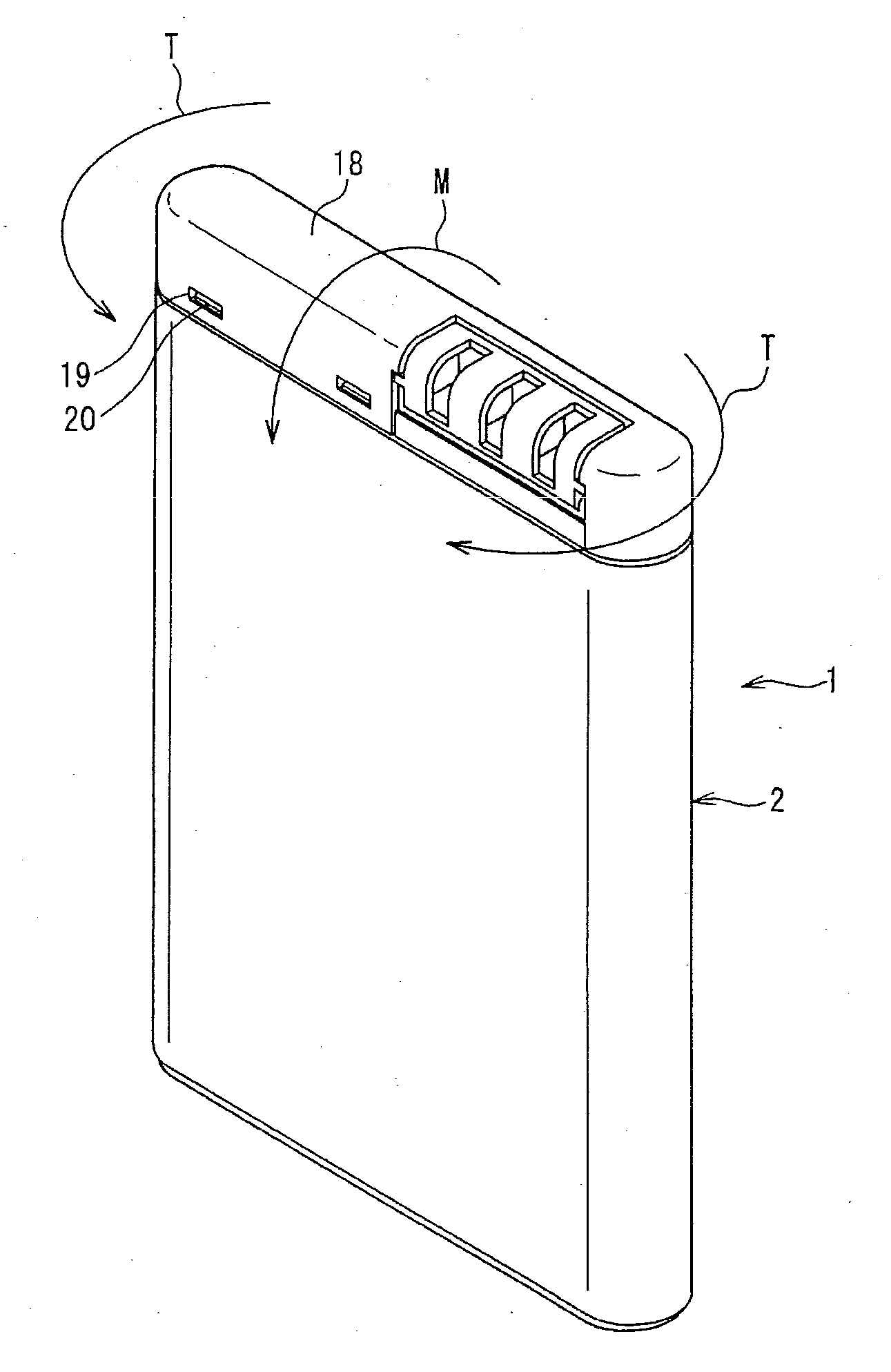
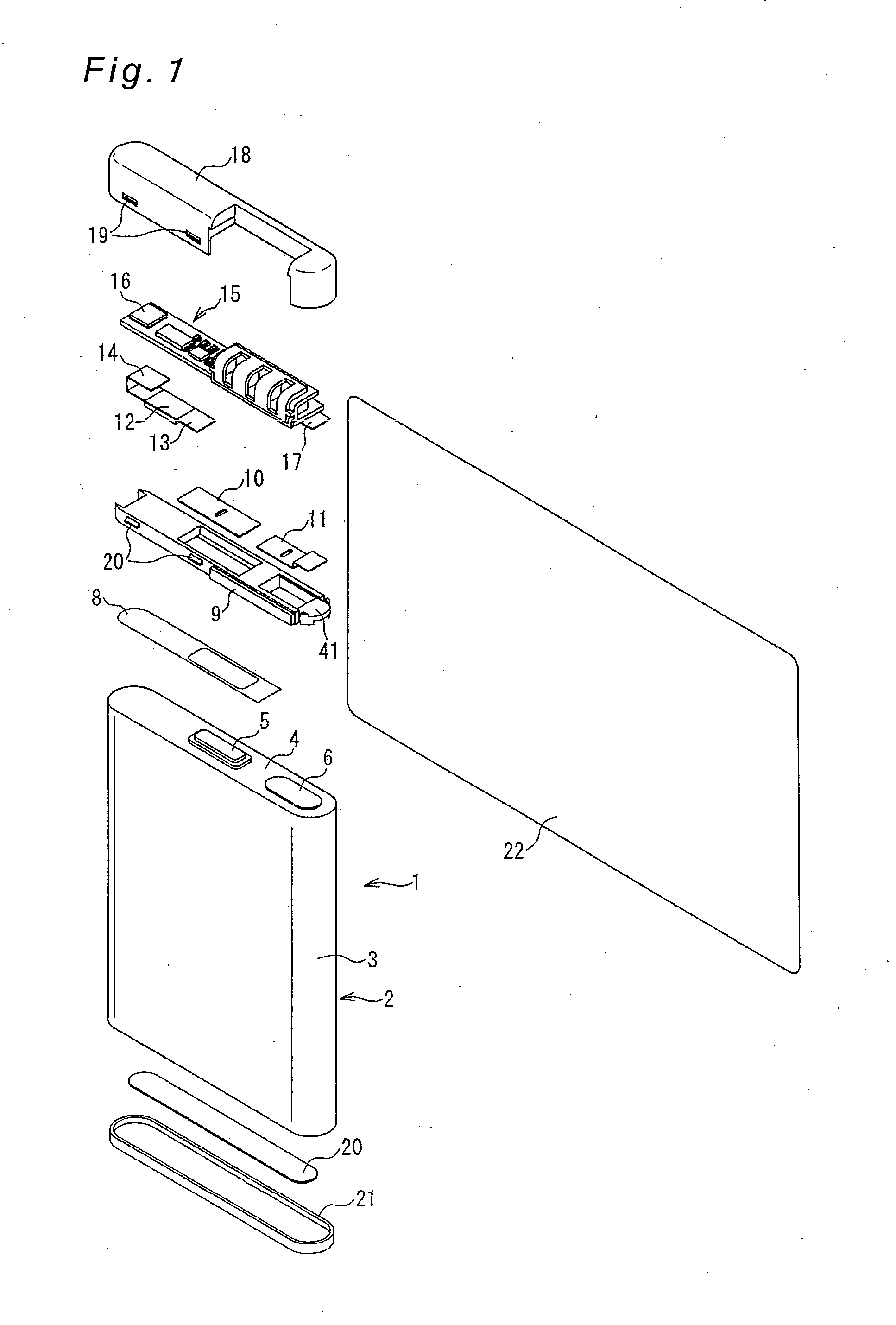
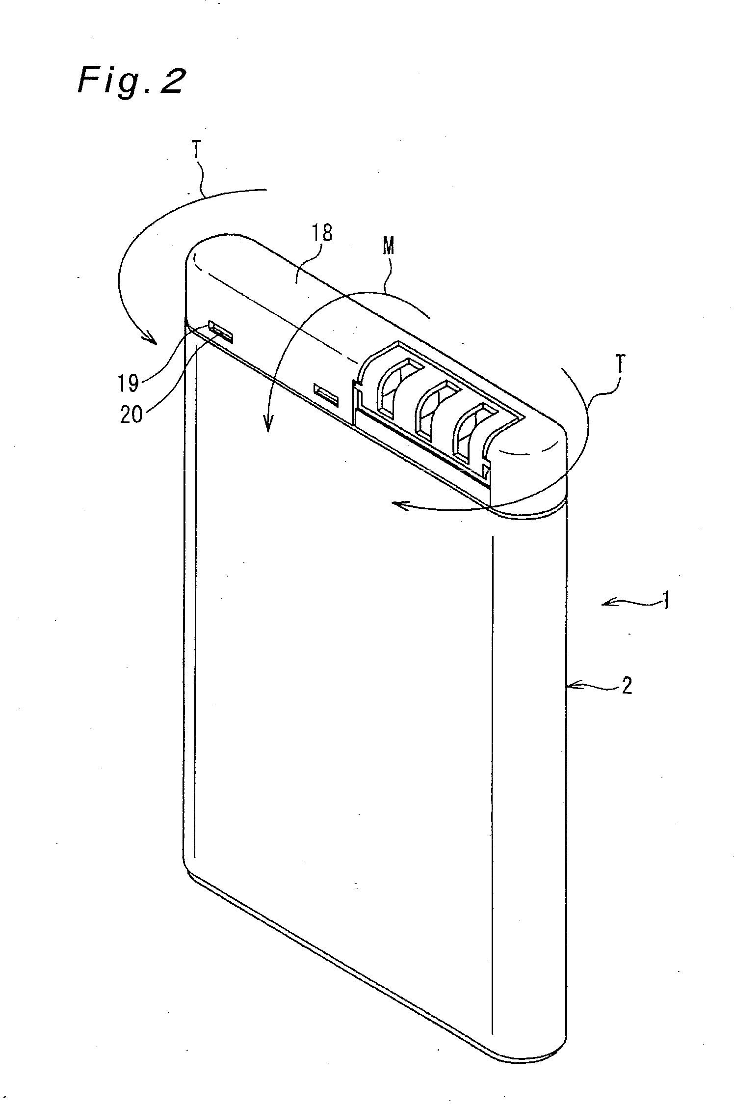
[0073]First, an outlined constitution of the battery pack is described with reference to FIG. 1. FIG. 1 is an exploded perspective view of a battery pack 1 according to one embodiment of the present invention. FIG. 1 shows a unit cell 2 and various accessory parts to be fitted thereto. The unit cell 2 is so made up that power generation elements are contained in a smaller-in-thickness, rectangular-shaped exterior case 3 formed from aluminum or aluminum alloy as an example. The unit cell 2 is a rectangular-shaped lithium ion battery, as an example, which is used in mobile phones, mobile equipment or the like. It is noted that the term “accessory parts” refers to various types of component parts for extracting electricity from the unit cell 2 to outside of the battery pack 1. Also, the battery pack 1 has a thinned flat quadrilateral shape whose depth is smaller in comparison to its longitudinal height and lateral length.

[0074]An opening portion of the exterior case 3 is sealed by a se...

second embodiment

[0110]A battery pack according to Embodiment 2 will be described below. Whereas two terminal portions are included in the unit cell 2 in Embodiment 1, three terminal portions are included in this embodiment. Due to this, the frame structure is changed with the lead count increased by one. Except for this point, this embodiment is similar in structure to Embodiment 1. Therefore, the same component members as in Embodiment 1 are designated by the same reference signs and their description is omitted.

[0111]FIG. 10 is an exploded perspective view of part of accessory parts in a battery pack 51 according to Embodiment 2. Shown in this figure are component parts involved up to the bonding of leads to a unit cell 52. Basic component members of the accessory parts after the bonding of the leads to the unit cell 52 are similar to those of Embodiment 1, and their description is omitted.

[0112]A third terminal 45 is provided in the sealing member 4 in addition to the negative terminal 5 and the...


PUM

PropertyMeasurementUnit
thicknessaaaaaaaaaa
sizeaaaaaaaaaa
heightaaaaaaaaaa

Abstract

In a battery pack in which accessory parts are fitted to a unit cell, the unit cell has a terminal portion, accessory parts include an electrical-connection use lead and a frame having an engagement portion to be engaged with the lead, and the lead and the terminal portion are bonded together by welding while the lead is engaged with the engagement portion. As a result of this, movement of the frame can be inhibited under action of external force. Moreover, in a structure in which an exterior cover is fitted to the frame or in which resin mold is integrally molded with the frame, movement of these members can be inhibited when external force acts on the exterior cover or the resin mold.

Description

BACKGROUND OF THE INVENTION[0001]1. Field of the Invention[0002]The present invention relates to a battery pack, as well as a manufacturing method therefor, in which leads for electrical connections are welded to its terminal portions.[0003]2. Description of Related Art[0004]With the trend toward thinner and smaller battery packs in recent years, there is a current tendency that, as the mainstream of battery packs, an positive lead and a negative lead are taken from the sealing side of a unit cell upper part so as to provide an exterior part in which a protective circuit and protective elements are integrated in upper part of the unit cell.[0005]FIG. 13 shows an exploded perspective view of an example of a conventional battery pack. The battery pack 120 shown in this figure, which is an example of an integrally molded structure that the exterior part is covered with a resin mold, has a thinned flat quadrilateral shape whose depth is smaller in comparison to its longitudinal height a...

Claims


Application Information

Patent Timeline
Patent Type & Authority Applications(United States)
IPC IPC(8): H01M2/30H01M2/00H01M50/528H01M50/55H01M50/553H01M50/562
CPCH01M2/30H01M2/34Y10T29/49108H01M10/0525H01M10/0436Y02E60/10H01M50/562H01M50/55H01M50/553H01M50/543H01M50/572H01M50/20
Inventor KAMADA, TATSUYASUMIDA, TAKASHIEBIHARA, HIDEAKI
Owner HITACHI MAXELL ENERGY LTD
Why Eureka
Try Eureka