Dual view endoscope

a dual-view, endoscope technology, applied in the field of endoscopes, can solve the problems of significant limitations of endoscopes, risky insertion of endoscopes into hollow organs, trauma, bleeding and perforation, etc., and achieve the effect of adequate distension

Inactive Publication Date: 2010-08-26
RATNAKAR NITESH
View PDF35 Cites 77 Cited by
  • Summary
  • Abstract
  • Description
  • Claims
  • Application Information

AI Technical Summary

Benefits of technology

[0011]The present invention enables rear view even in organs with a narrow lumen without the need to retro flex the endoscope. This is achieved by strategically adding a suitably designed ‘rear view module’ to a conventional endoscope. The rear view module consists of a rear image lens and a rear illumination bulb. The rear view module is a solid or tubular structure that can be of different shapes, sizes and configurations as illustrated in the preferred embodiments of the present invention. It is attached to the endoscope in different ways as illustrated in the preferred embodiments of the present invention. Once deployed, the rear view module positions the rear image lens and the rear illumination bulb facing backward. In this position, the rear illumination bulb illuminates the rear area and the rear image lens gives a rear view. The rear image lens is connected to an image processor and the rear illumination bulb is connected to a light source by electrical cables. The rear image lens and the rear illumination bulb can be used simultaneously or separately from the main image lens and the main illumination bulb, as chosen by the operator. Simultaneous forward and rear view can thus be obtained by using the forward image lens and the rear image lens together at a given time. This has the advantage of allowing a thorough examination of a hollow organ that includes both forward and rear views in a single passage.
[0013]The present invention has a rear air / water channel and a rear air / water nozzle located on the shaft of the endoscope. The rear air / water channel is connected to the main air / water channel of the endoscope and the connecting passage has a control valve. Typically, deployment of the rear view module automatically opens the passage to the rear air / water channel. Alternatively, the valve can be controlled independently. The rear air / water channel enables the operator to insufflate air and distend the area under the view of rear image lens. Adequate distension of a hollow organ is essential to obtain a clear and complete view. The rear air / water channel also provides a water jet and a stream of air to clean the rear image lens and rear illumination bulb while inside a hollow body organ.

Problems solved by technology

Insertion of the endoscope into a hollow organ is a risky maneuver and is associated with significant complications like trauma, bleeding and perforation.
The present endoscopes have significant limitations.
However, it is not possible to achieve retro flexion in many narrow hollow organs like colon, esophagus, duodenum and small bowel.
Also, retro flexion compromises forward view.
A large number of significant pathologic findings are frequently missed during endoscopic examination because the inability to obtain rear view and a narrow field of vision of conventional endoscopes.
However, it is frequently not possible to achieve retro flexion in a narrow hollow organ like colon.
Also, retro flexion maneuver compromises the forward view.
Both, retro flexion and multiple insertions, independently increase the morbidity, mortality, time and cost of colonoscopy.
Moreover, intra colonic retro flexion can not be obtained frequently because of a narrow colonic lumen.
The rear side of the mucosal folds is also hard to access with conventional endoscopes, which have the instrument channel outlet only on the distal end.
Also, many surgical instruments are not flexible enough to follow the path of a retroflexed endoscope.
It is difficult and many times impossible to pass surgical instruments through the instrument channel when the endoscope is retroflexed and surgical procedures can not be performed on the rear side of the mucosal folds.

Method used


Image

  • Dual view endoscope
  • Dual view endoscope
  • Dual view endoscope

Examples


Embodiment Construction

[0045]Reference will now be made in detail to the preferred embodiments of the invention, examples of which are illustrated in the accompanying drawings. Wherever possible, the same reference numbers will be used throughout the drawings to refer to the same or like parts. The following general description applies to preferred embodiments of the present invention.

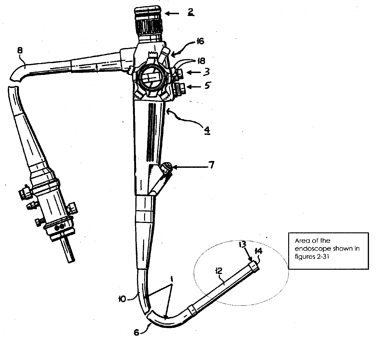
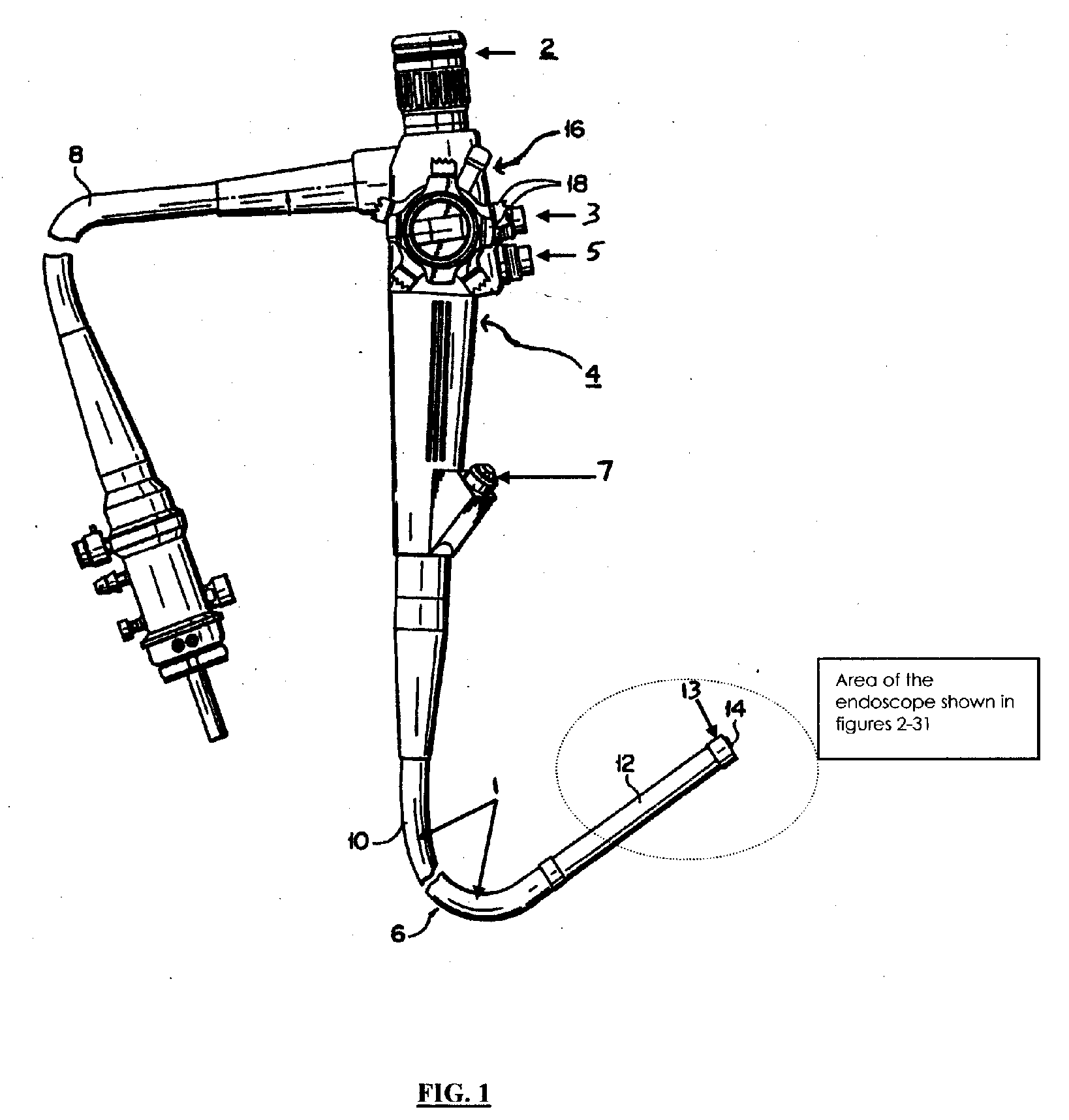
[0046]The present invention comprises of a rear view module. It is a solid structure that can be rectangular, square, tubular, discoid or of any other shape. It is attached to a conventional endoscope by a suitable mechanical articulation such as ball socket joint, hinge joint, biplanar rolling joint etc. The rear view module consists of a rear image lens to obtain a rear view. The rear image lens is attached to an image processor by an electric cable. This cable transmits the image obtained by the rear image lens to the image processor. After being processed, the image is then viewed on a computer monitor or any other displ...


PUM


Abstract

The present invention relates to an endoscope, more specifically to an endoscope that provides both forward view and rear view of a hollow body organ. It comprises of a rear view module that contains a rear image lens and a rear illumination bulb. The rear view module is designed and is attached to a conventional endoscope in a way that when deployed, the rear image lens and the rear illumination bulb face backward. In this position, the rear image lens provides a rear view and the rear illumination bulb illuminates the area under view of the rear image lens. The present invention enables the operator to obtain forward and rear views of a hollow organ either separately or simultaneously. The ability to obtain forward and rear view at the same time enables the operator to perform a complete examination of a hollow organ that includes both forward and rear view in a single insertion.The present invention enables surgical procedures to be performed in areas that are otherwise inaccessible and out of view of conventional endoscopes. This is made possible by a rear instrument channel located proximal to the rear view module. The present invention also improves distension and visualization of a hollow internal organ by having a rear air / water channel also located proximal to the rear view module. The present invention widens the field of vision of conventional endoscopes by enabling the addition of more than one forward image lens and more than one forward illumination bulb.

Description

FIELD OF INVENTION[0001]The present invention relates to endoscopes, more specifically to endoscopes that provide both forward and rear view in a hollow body organ.BACKGROUND AND PRIOR ART[0002]Endoscopes are used to perform a variety of surgical procedures. FIGS. 1 and 2 illustrate an embodiment of a conventional endoscope. It has a handle from which extends a flexible shaft, which is inserted into a hollow organ to be inspected. The shaft consists of a proximal section, insertion tube, bending section and a stiff section. The shaft terminates in the distal end, which typically houses image lens, illumination bulb, air / water nozzle and an instrument channel outlet. Light is transmitted from a light source through the shaft via an electric cable to the illumination bulb. The illumination bulb illuminates the area to be examined. The image lens captures images of the illuminated area. The image is then transmitted through a fiber optic cable and viewed through an eyepiece on the hand...

Claims


Application Information

Patent Timeline
Patent Type & Authority Applications(United States)
IPC IPC(8): A61B1/06A61B1/00A61B1/005A61B1/12
CPCA61B1/00105A61B1/00179A61B1/00181A61B1/0051A61B1/00174A61B1/12A61B1/0623A61B1/0676A61B1/0125A61B1/0627A61B1/00096A61B1/015A61B1/00114A61B1/126A61B1/00091A61B1/018
Inventor RATNAKAR, NITESH
Owner RATNAKAR NITESH
Why Eureka
Try Eureka