Disk carrying device and optical disk recording/reproducing device

a technology of optical disk and carrying device, which is applied in the direction of recording information storage, instruments, etc., can solve the problems of uneven disk carrying and relatively high motor load, and achieve the effects of reducing power consumption, reducing the load on the disk carrying motor, and reducing the heat from the motor

Active Publication Date: 2010-08-26
PANASONIC CORP
View PDF4 Cites 1 Cited by
  • Summary
  • Abstract
  • Description
  • Claims
  • Application Information

AI Technical Summary

Benefits of technology

[0010]The present invention is to solve the conventional problem as described above and its object is to provide a disk carrying device capable of reducing the load on a motor to smoothly carry a disk, and to provide an optical disk recording / reproducing device having the same.
[0012]Because of this configuration, the second idle gear, which is supported together with the roller gear by the feed plate, contacts and separates from the first idle gear along with the swinging of the feed plate. Thus, in the disk insertion, when the drive force from the disk carrying motor is transmitted from the worm gear to the first idle gear and is transmitted from the first idle gear to the second idle gear, the downward force is applied to the second idle gear by the first idle gear and the downward force acts on the feed roller via the roller gear. When the disk has been completely carried to the depth side of the device and when the feed roller slips, the pushing pressure of the feed roller to the disk decreases and the load on the disk carrying motor is reduced. Thus a low output motor can be adopted. In this way, the power consumption decreases and the heat from the motor is suppressed, so that the gears can be made of a relatively soft resin material as the temperature-resistance characteristic is improved and the forces on the gears decrease. Consequently it is possible to reduce gear noise from gear meshing sound. Further, in the disk ejection, the upward force is applied to the second idle gear from the first idle gear and the upward force acts on the feed roller via the roller gear, so that the pushing pressure of the feed roller to the disk increases. Thus the disk ejecting force can be increased. In this way, it is possible to smoothly carry the disk, regardless of the warping of the disk and the friction coefficient of the disk surface.
[0013]The present invention is to provide a disk carrying device where a gear array for transmitting a drive force of a disk carrying motor to a feed roller, includes: a worm gear for transmitting a torque of the disk carrying motor; a first idle gear rotatably supported by a lower chassis to transmit the torque from the worm gear; a second idle gear rotatably supported by a feed plate and being detachably engaged with the first idle gear; and a roller gear fixed to a roller shaft of the feed roller to mesh with the second idle gear. Because of this configuration, in the disk insertion, a downward force from the first idle gear is applied to the second idle gear and the downward force acts on the feed roller via the roller gear, so that a pushing pressure of the feed roller to the disk decreases and a load on the disk carrying motor is reduced. Thus a low output motor can be adopted. In addition, there is an advantage that in the disk ejection, an upward force from the first idle gear is applied to the second idle gear and the upward force acts on the feed roller via the roller gear, so that the pushing pressure of the feed roller to the disk increases, and thus the disk ejecting force can be increased.

Problems solved by technology

However, in the above described conventional disk carrying device, there has been a problem that the motor load relatively increases as a disk carrying force by the feed roller 14 is strong in insertion, and that the disk is not smoothly carried as the disk carrying force is weak in ejection.

Method used


Image

  • Disk carrying device and optical disk recording/reproducing device
  • Disk carrying device and optical disk recording/reproducing device
  • Disk carrying device and optical disk recording/reproducing device

Examples


Embodiment Construction

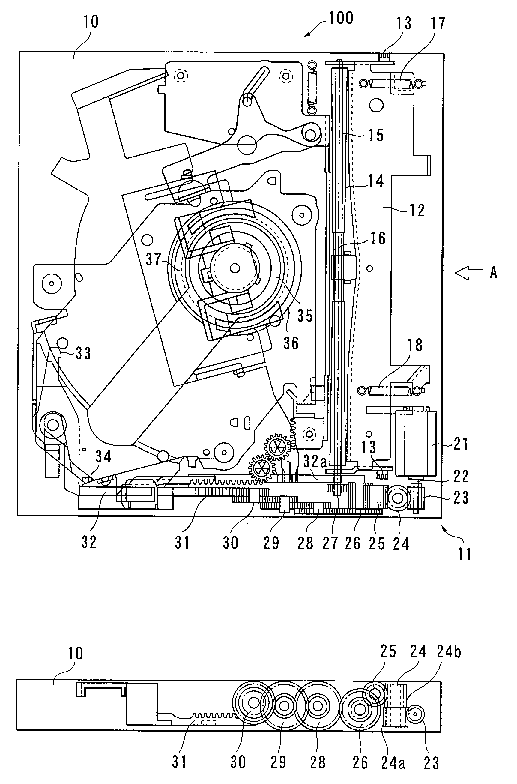
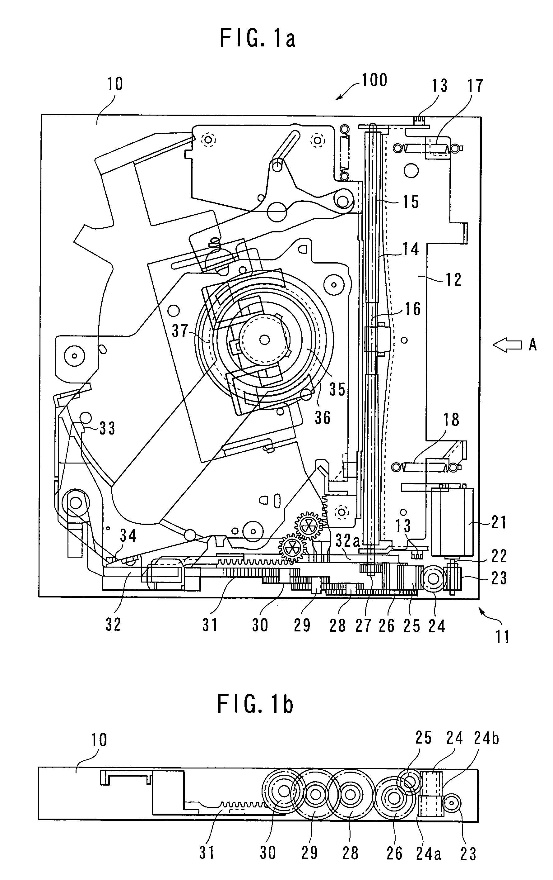
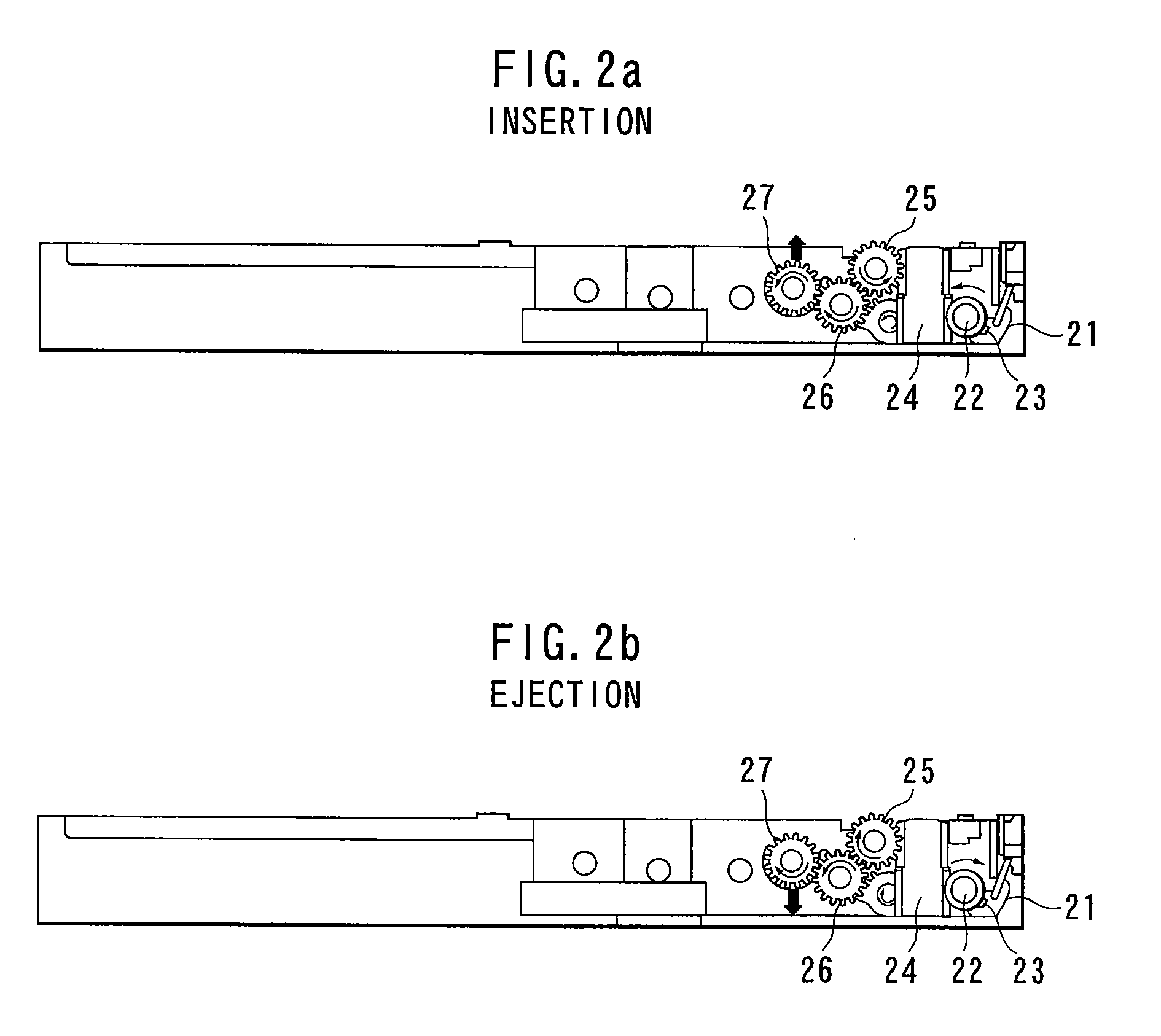
[0019]Hereinafter, a preferred embodiment of the present invention will be described with reference to accompanying drawings. FIG. 3 is a schematic top view of a lower chassis of an optical disk recording / reproducing device for automobile use having a disk carrying device in an embodiment of the invention. FIGS. 4A and 4B are schematic side views in the disk carrying device. The general configuration and operation of the optical disk recording / reproducing device in the embodiment is similar to the conventional example shown in FIGS. 1A, 1B and FIGS. 2A, 2B, and only the configuration of the disk carrying device is different from the conventional example. Thus, for illustrative convenience, the similar components are designated by the reference numerals used for the description of the conventional example shown in FIGS. 1A, 1B and FIGS. 2A, 2B.

[0020]In FIG. 3 and FIGS. 4A, 4B, a disk carrying device 11 is provided in a front portion of a lower chassis 10 within an optical disk record...


PUM

PropertyMeasurementUnit
torqueaaaaaaaaaa
sizeaaaaaaaaaa
thicknessaaaaaaaaaa

Abstract

A disk carrying device and an optical disk recording / reproducing device. The disk carrying device comprises a first idle gear rotatably supported on a lower chassis and a second idle gear rotatingly operated by coming into contact with or separating from the first idle gear. The second idle gear and a roller gear meshed with the second idle gear are rotatably supported on a feed plate, and the second idle gear is brought into contact with or separated from the first idle gear, from the underside, which is rotatably supported on the lower chassis. By this, when a disk is inserted, a downward force F1 acts on the second idle gear, and the pressing force of a feed roller on the disk (D) is decreased and, therefore, the rotating load of a disk carrying motor can be reduced when the carrying of the disk is completed. When the disk is discharged, an upward force F2 acts on the second idle gear and the pressing force of the feed roller on the disk (D) is increased and, therefore, the disk (D) can be smoothly discharged even if the disk (D) is deflected.

Description

BACKGROUND OF THE INVENTION[0001]1. Technical Field of the Invention[0002]The present invention relates to a disk carrying device for carrying a disk by a rotatable feed roller and to an optical disk recording / reproducing device having the disk carrying device.[0003]2. Description of the Related Art[0004]In the field of optical disk recording / reproducing device, particularly optical disk recording / reproducing device for automobile use, there has been a strong demand from the market for the size and thickness reduction, and technology for realizing this is being actively developed. In order to achieve the size and thickness reduction of the optical recording / reproducing device, there is adopted a method of carrying an optical disk directly held by a feed roller and a disk guide therebetween when the optical disk is inserted into and ejected from a device, rather than a method of placing the optical disk on a tray (see, for example, Patent Document 1).[0005]FIG. 1A is a schematic top ...

Claims


Application Information

Patent Timeline
Patent Type & Authority Applications(United States)
IPC IPC(8): G11B17/04G11B17/051
CPCG11B17/05G11B17/0404
Inventor INOUE, TAKASHIHINO, YUTAKATAKAHASHI, JUNYAKOBAYASHI, HIROKIITO, TATUO
Owner PANASONIC CORP
Why Eureka
Try Eureka