Gripper for an automated manipulator and method for operation of the gripper

Inactive Publication Date: 2010-09-02
KUKA ROBOTER
View PDF11 Cites 9 Cited by
  • Summary
  • Abstract
  • Description
  • Claims
  • Application Information

AI Technical Summary

Benefits of technology

[0032]In a preferred embodiment, an angle flange of the support base is arranged along the insertion axis on the side of the clamp stop facing away from the counter-stop so that the clamp stop is accommodated between counter-stop and angle flange. A support pla

Problems solved by technology

A disadvantage of this known gripper is that the bundle take-up and placement possibilities of this gripper are limited.
For example, due to the insertion movement of the support bases from the outside on both sides a bund

Method used


Image

  • Gripper for an automated manipulator and method for operation of the gripper
  • Gripper for an automated manipulator and method for operation of the gripper
  • Gripper for an automated manipulator and method for operation of the gripper

Examples


Embodiment Construction

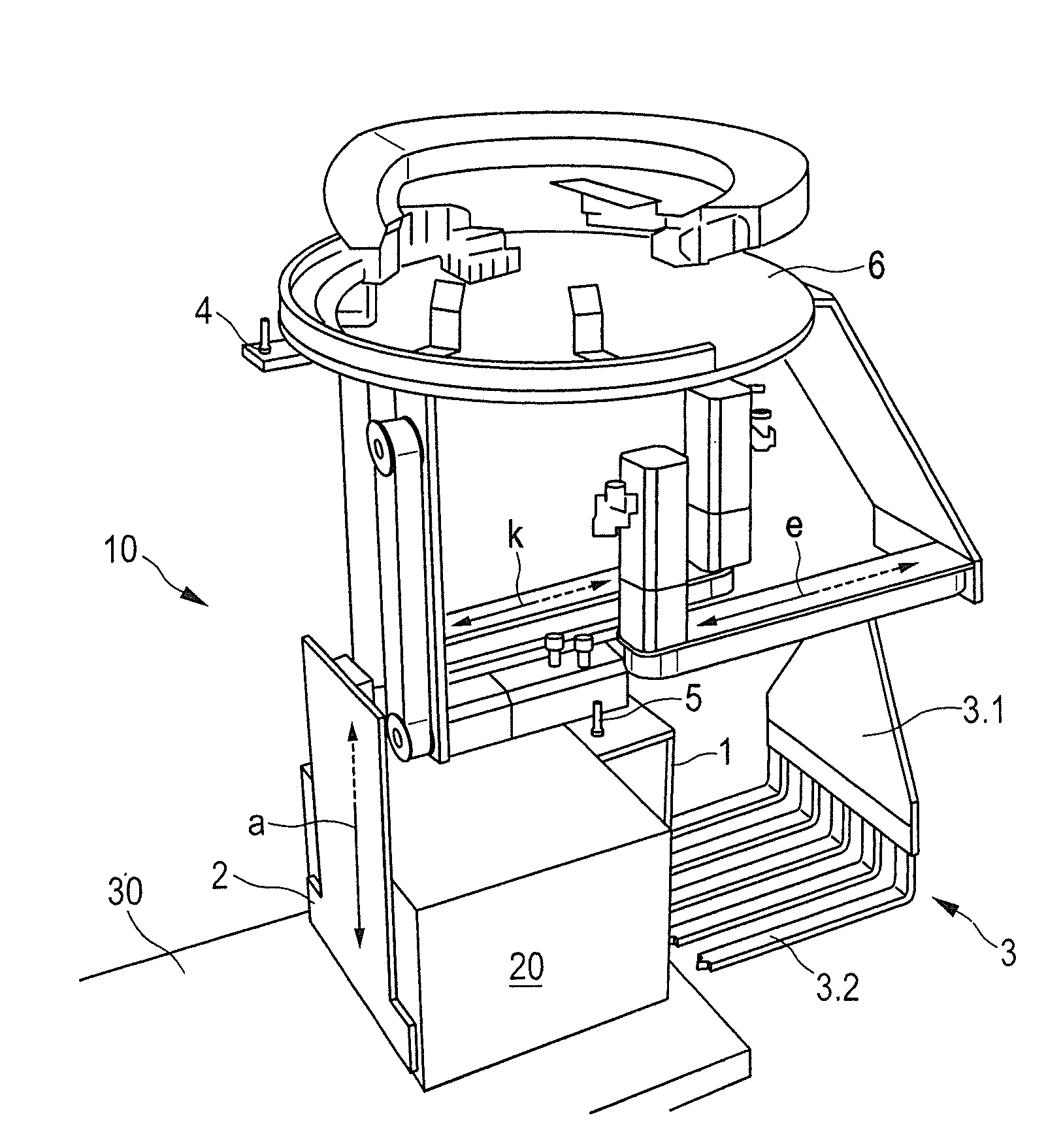
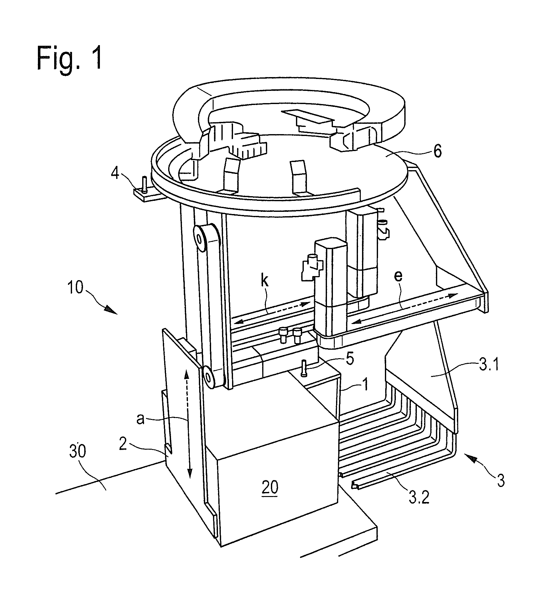
[0041]FIG. 1 shows a manipulator gripper 10 for palletizing and depalletizing bundles 20 by means of an articulated arm robot (not shown). It comprises a tool flange 6 for connection to the articulated arm robot. A trailing cable installation enables rotation movements by ±225°.

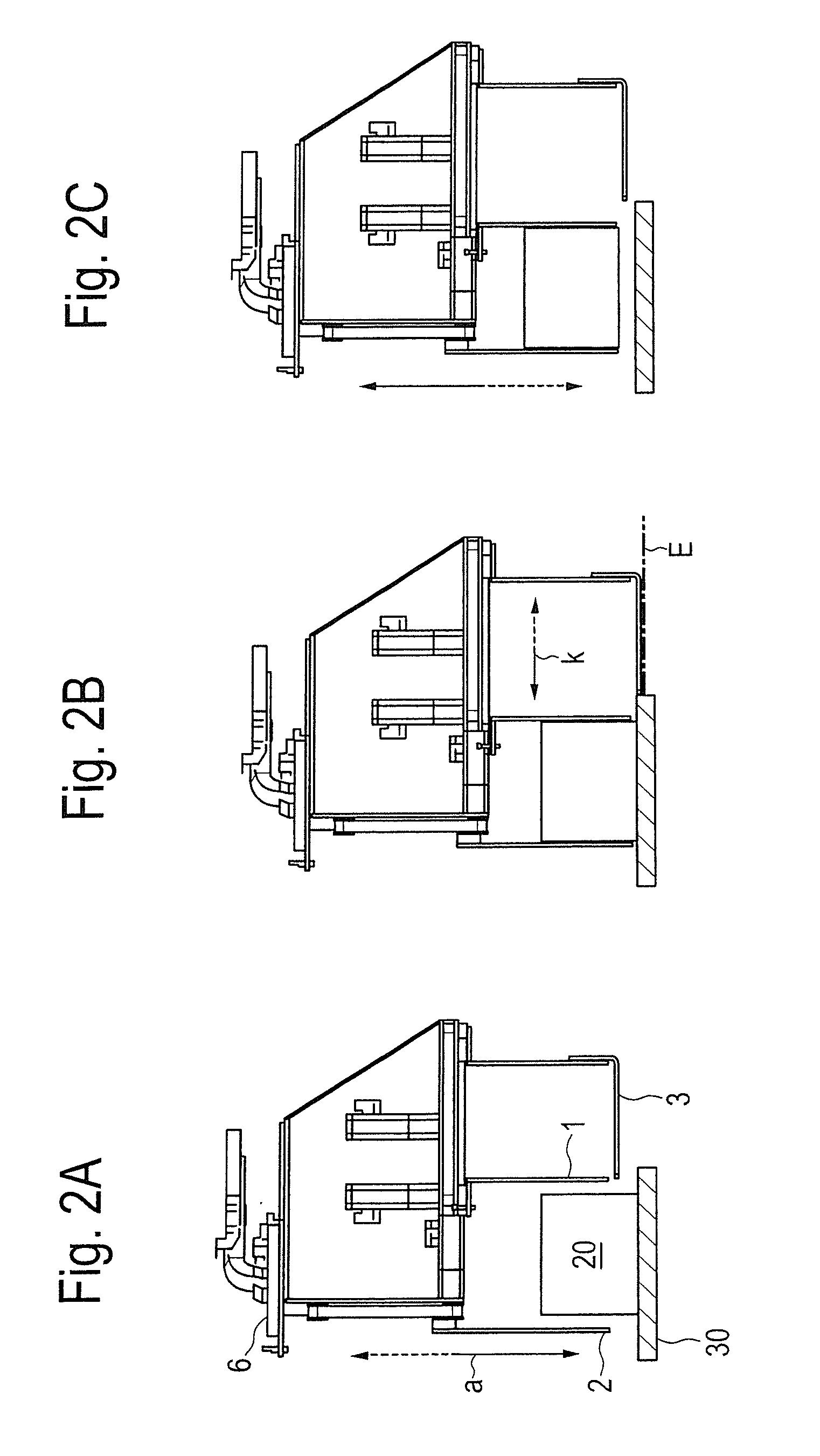
[0042]A bent support base 3 with its angle flange 3.1 is borne on the tool flange 6 such that said support base 3 can be shifted, and extends with a support plate 3.2 in an insertion plane E (see FIG. 2B) towards a counter-stop 2. This can be shifted on a lowering axis a towards the insertion plane E of the support base 3. A clamp stop 1 extends parallel to the counter-stop 2 along the lowering axis a and can be shifted relative to the tool flange 6 and the support base 3 along a clamp axis k towards the counter-stop 2. The support base 3 can be shifted, relative to the tool flange 6, towards the counter-stop 2 in the insertion plane E along an insertion axis essentially parallel to the clamp axis k.

[0043]Low...


PUM

PropertyMeasurementUnit
Shapeaaaaaaaaaa
Distanceaaaaaaaaaa

Abstract

A manipulator gripper in particular for palletizing and/or depalletizing bundles by means of a robot, has a tool flange for connection to a manipulator; a clamp stop and a counter-stop. Both extend along a lowering axis. A support base extends toward the counter-stop in an insertion plane. The counter-stop and/or the clamp stop can be shifted toward the insertion plane of the support base along the lowering axis, relative to the tool flange.

Description

BACKGROUND OF THE INVENTION[0001]1. Field of the Invention[0002]The invention concerns a manipulator gripper, in particular for palletizing and / or depalletizing bundles by means of a robot, as well as a method for handling a bundle by means of an automated manipulator with such a gripper.[0003]2. Description of the Prior Art[0004]In many fields, one or more layers of goods bundles—that, for example, can be bound in containers, on trays or by packing means or packing aids (such as films)—of individual goods are stacked on conveyors (for example belt, chain or roller conveyors) as well as on transport aids (in particular pallets, table shelves or the like) and are therefore assembled, for example for transport, storage or sale. A layer or partial layer of such individual goods and / or goods bundles (in particular also an individual good or a goods bundle alone) is subsequently uniformly designated as a bundle.[0005]Typical examples are homogeneous or mixed stacks of drink cases, Tetrap...

Claims


Application Information

Patent Timeline
IPC IPC(8): B65B11/02
CPCB65G61/00
Inventor BAUMANN, MICHAEL
Owner KUKA ROBOTER
Why Eureka
Try Eureka