Turbine engine compressor

a compressor and turbine engine technology, applied in the direction of gearing details, machines/engines, gearing, etc., can solve the problem fan speed that is not suitable for use, and achieve the effect of low spool speed

Inactive Publication Date: 2010-09-02
RAYTHEON TECH CORP
View PDF10 Cites 31 Cited by
  • Summary
  • Abstract
  • Description
  • Claims
  • Application Information

AI Technical Summary

Benefits of technology

[0004]One aspect of the invention involves compensating for low spool speed by providing a compressor with at least one counter-rotating blade stage in lieu of a stator stage. Thus, a first spool may have at least one compressor blade stage and at least one turbine blade stage. A combustor is located between the at least one compressor...

Problems solved by technology

In designing an engine, there may be a mismatch be...

Method used


Image

  • Turbine engine compressor
  • Turbine engine compressor
  • Turbine engine compressor

Examples


Embodiment Construction

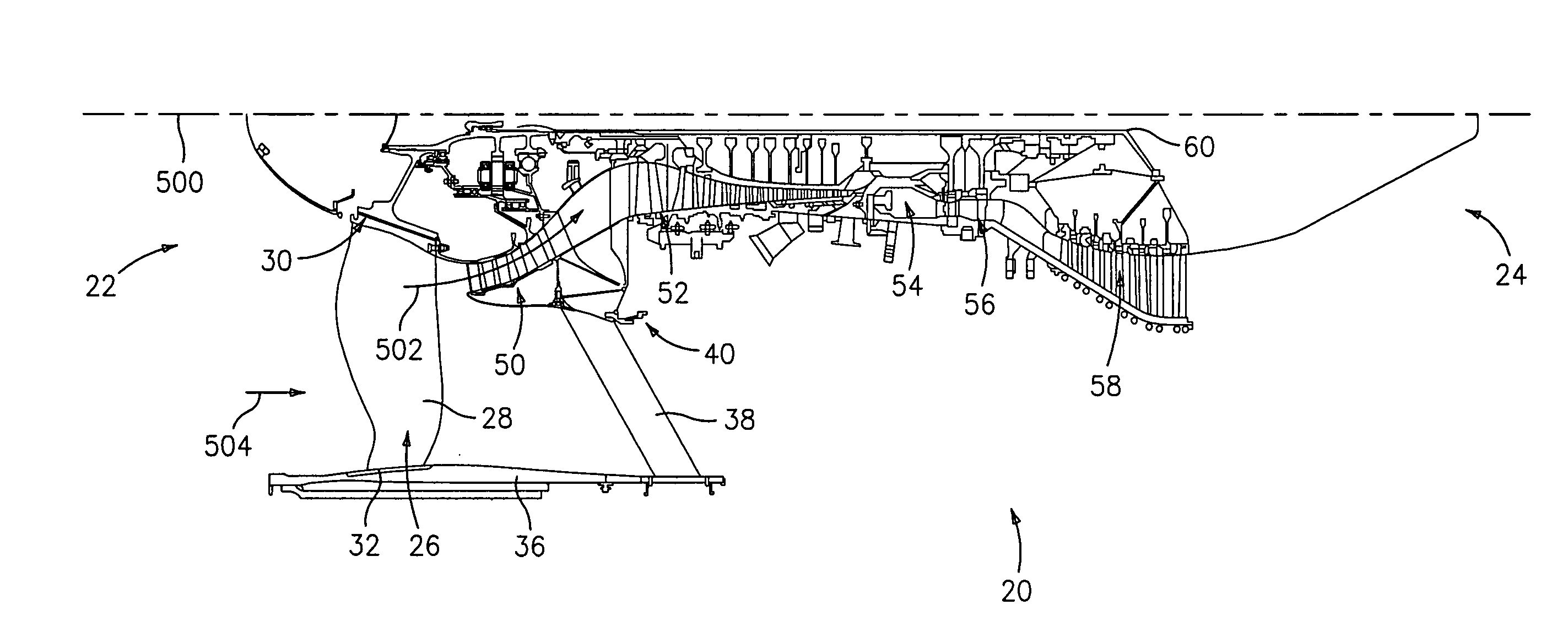
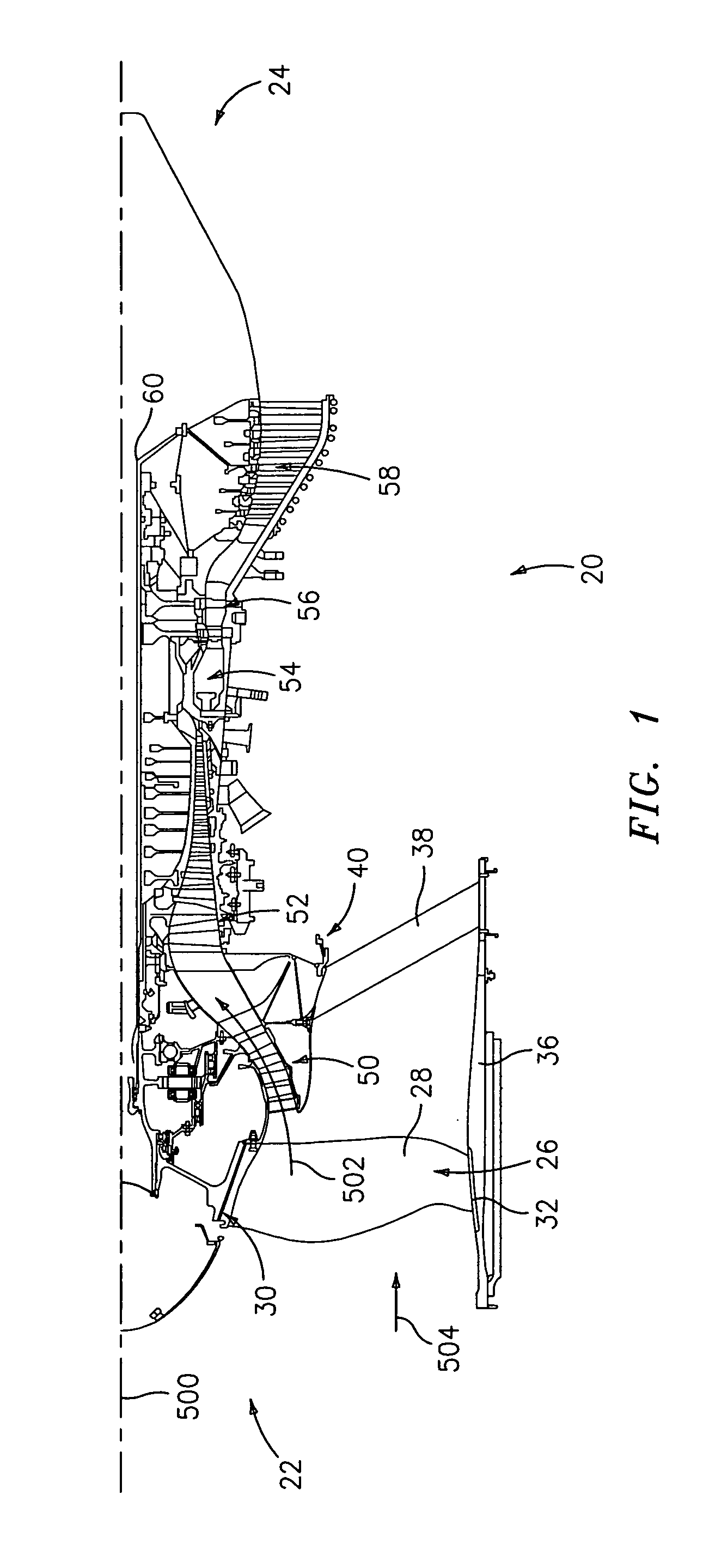
[0011]FIG. 1 shows a turbofan engine 20 having a central longitudinal axis 500. The engine has a core flowpath 502 and a bypass flowpath 504. The engine has a forward / inlet / upstream end 22 and an aft / outlet / downstream end 24. At upstream ends of the core and bypass flowpaths, the engine has a fan 26 comprising a circumferential array of blades 28 extending from inboard platforms 30 to outboard tips 32. The exemplary tips are closely spaced apart from the inboard surface of a shroud 36. The shroud may be held by a circumferential array of struts 38 extending from a structural case 40.

[0012]Proceeding downstream along the core flowpath 502, the engine has a low pressure compressor (LPC) section 50, a high pressure compressor (HPC) section 52, a combustor section 54, a high pressure turbine (HPT) section 56, and a low pressure turbine (LPT) section 58. The exemplary engine includes a low speed spool shaft 60. An exemplary high speed spool may be formed as a rotor stack (e.g., without a...


PUM


Abstract

A counter-rotating blade stage in lieu of a stator stage may compensate for relatively low rotational speed of a gas turbine engine spool. A first spool may have at least one compressor blade stage and at least one turbine blade stage. A combustor is located between the at least one compressor blade stage and the at least one turbine blade stage along a core flowpath. The at least one counter-rotating compressor blade stage is interspersed with the first spool at least one compressor blade stage. A transmission couples the at least one additional compressor blade stage to the first spool for counter-rotation about the engine axis.

Description

BACKGROUND OF THE INVENTION[0001]The invention relates to gas turbine engines. More particularly, the invention relates to low pressure compressor sections of multi-spool turbofan engines.[0002]A gas turbine engine may have one or more spools. Each spool may, for example, include the blades of associated compressor and turbine sections and a connecting shaft. Two- and three-spool engines are known. An exemplary two-spool engine included low and high speed spools. At cruise conditions, exemplary low spool speeds are 2000-7000 revolutions per minute (RPM) while exemplary high spool speeds are 9000-21000 RPM. The low spool includes low speed / pressure compressor and turbine (LPC and LPT) blades while the high spool includes high speed / pressure compressor and turbine (HPC and HPT) blades. A core flowpath through the engine may sequentially pass through the LPC, HPC, combustor, HPT, and LPT.[0003]In a turbofan engine, a fan drives air along a bypass flowpath. In many engines, the fan may ...

Claims


Application Information

Patent Timeline
IPC IPC(8): F02K3/00F16H1/28
CPCF02C3/067F02C3/107F05D2260/40311F05D2260/40F02K3/072
Inventor MERRY, BRIAN D.SUCIU, GABRIEL L.NIKKANEN, JOHN P.
Owner RAYTHEON TECH CORP
Why Eureka
Try Eureka