Particulate filter and method of use

a technology of particle filter and filter body, which is applied in the direction of membranes, separation processes, instruments, etc., can solve the problems that no known particulate filter has been designed to address specifically improved performance and stability, and achieve improved efficiency and permeability, improved relative humidity stability, and improved moisture stability

Inactive Publication Date: 2010-09-02
MEASUREMENT TECH LAB CORP
View PDF20 Cites 16 Cited by
  • Summary
  • Abstract
  • Description
  • Claims
  • Application Information

AI Technical Summary

Benefits of technology

[0011]The particulate filter and methods of the invention thereby provide various advantages, such as one or more of improved efficiency and permeability, improved moisture stability, improved relative humidity stability, improved static stability, a ringed or ring-less design for improved handling, and the optional functionality of being printable with an identification symbol or code to facilitate automated filter handling and weighing in some embodiments. Embodiments of the particulate filter device of the invention simplify the discharge of electrostatic charge buildup, provide improved identification methods and means, and may be used to accurately measure particulate pollutants and materials.

Problems solved by technology

To date no known particulate filter has been designed to address specifically improved performance, stability, and usability at the microgram and sub microgram level and for various applications.

Method used


Image

  • Particulate filter and method of use
  • Particulate filter and method of use
  • Particulate filter and method of use

Examples


Embodiment Construction

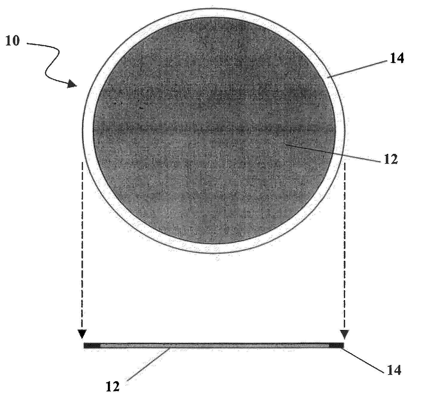
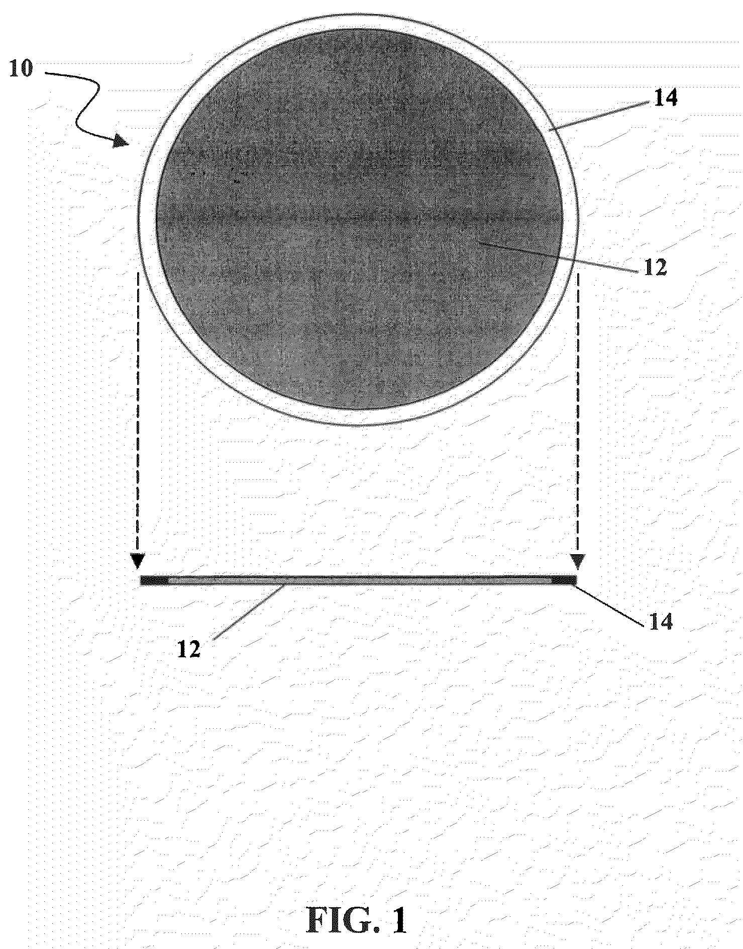
[0019]The present invention is directed to a particle sampling test filter that can be used, for example, as a particle sampling filter in diesel emissions testing, and the methodology of use of the particle sampling test filter. The particle sampling filter of the invention provides various advantages, such as one or more of improved efficiency and permeability, improved moisture stability, improved relative humidity stability, improved static stability, a ringed or ring-less design for improved handling, and the optional functionality of being printable with an identification symbol or code to facilitate automated filter handling and weighing in some embodiments. Embodiments of the particulate filter device of the invention simplify the discharge of electrostatic charge buildup, provide improved identification methods and means, and may be used to accurately measure particulate pollutants and materials.

[0020]Embodiments of the invention have applicability in a wide range of applic...


PUM

PropertyMeasurementUnit
particle diametersaaaaaaaaaa

Abstract

A particulate filter particularly suited for analytical gravimetric weighing applications is disclosed. The particulate filter includes a polytetrafluoroethylene (PTFE) media supported by a ring and yields stable microgram and submicrogram weighing results. The support ring may be PTFE, metal foil, or another non-hygroscopic polymer such that the mass of the filter does not vary with changes in atmospheric moisture. The filter simplifies the discharge of electrostatic charge buildup such that when a conductive filter media is combined with a conductive ring device, the discharge may be accomplished by placing the filter on a grounded weighing pan or other surface. The particulate filter can simplify filter identification by including identification symbols imprinted on each side of the filter media. Due to the chemically inert qualities of its components, the particulate filter is particularly suited for extraction techniques used during the detection of polycyclic hydrocarbons as is conducted in emissions and ambient air testing.

Description

RELATED APPLICATIONS[0001]This application is a continuation of application Ser. No. 11 / 060,080, filed Feb. 16, 2005, which claims the benefit of U.S. Provisional Application No. 60 / 545,296, filed Feb. 16, 2004, and U.S. Provisional Application No. 60 / 549,076, filed Mar. 1, 2004, which applications are incorporated herein by reference in their entirety.BACKGROUND OF THE INVENTION[0002]Particulate filters have long been known and widely used. Particulate filters of various types have been utilized for decades in different applications, for example air filtration and analytical measurements in laboratories for a wide range of testing protocols.[0003]Of recent importance is a method of gravimetric analysis. Gravimetric analysis is founded on the principle that a weight of a substance is the elementary measurement used for calculation. In the case of gravimetric analysis of particulate filter applications, the results of a weighing before (pre weighing) and after (post weighing) exposur...

Claims


Application Information

Patent Timeline
Patent Type & Authority Applications(United States)
IPC IPC(8): G01N1/22B01D63/02B01D63/08B01D69/02B01D69/10B01D71/36G01N1/00G01N5/02G01N15/00G01N15/06G01N35/00
CPCB01D39/1692B01D2313/025B01D63/08B01D69/02B01D69/10B01D71/36B01D2325/00B01D2325/02B01D2325/04B01D2325/20B01D2325/38G01N1/2205G01N1/2252G01N5/02G01N15/0618G01N35/00732G01N2015/0046G01N2035/00772B01D63/021
Inventor DIKKEN, DAVID A.NELSON, ROBERT O.KELENY, LLOYD G.KIESTER, MIKEDAHLGREN, ANDREW
Owner MEASUREMENT TECH LAB CORP
Why Eureka
Try Eureka