Tripod mount and clamp assembly

a technology of clamping and tripod, which is applied in the direction of rod connection, force/torque/work measurement apparatus, instruments, etc., can solve the problems of inconvenient and difficult use, inconvenient and difficult to use, and inability to hold a firearm consistently in a set position without wavering, and achieves undesirable machining or modification of the firearm stock to accommodate the bipod

Inactive Publication Date: 2010-09-02
KENGS FIREARMS SPECIALTY
View PDF18 Cites 33 Cited by
  • Summary
  • Abstract
  • Description
  • Claims
  • Application Information

AI Technical Summary

Benefits of technology

[0012]In use, the telescoping legs of the tripod assembly of the present invention can be retracted and pivoted to a horizontal, non-supportive, or folded position or can be deployed into a substantially vertical, supporting position, with the telescoping legs optionally extended as needed to adjust the height of the tripod support. With the optional Versa-Pod® style clamp assembly securely mounted to the tripod assembly

Problems solved by technology

Most shooters are not able to hold a firearm consistently in a set position without wavering, especially after the onset of fatigue resulting from strain on the shooter due to the size and weight of the firearm.
Early bipod and tripod supports typically were somewhat crude stands that generally were bulky, inconvenient and difficult to use and typically were not easily adjustable.
Problems sometimes noted with conventional bipods include stability and the ability of the bipod to mount to most firearms without requiring the use of special mounting tools.
Machining or modification of the firearm stock to accommodate the bipod is undesirable, for most users.
Additionally, most supports are not designed for quick and easy attachment and release from the firearm stock.
F

Method used


Image

  • Tripod mount and clamp assembly
  • Tripod mount and clamp assembly
  • Tripod mount and clamp assembly

Examples


Embodiment Construction

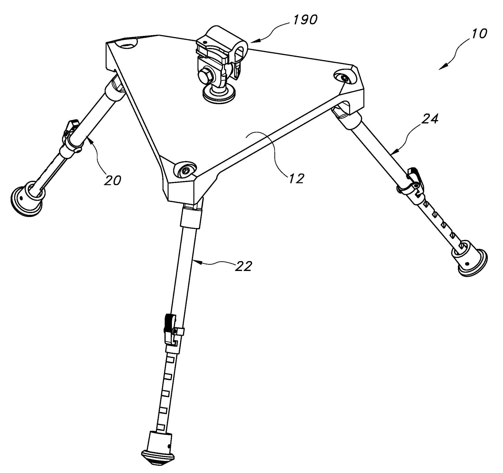
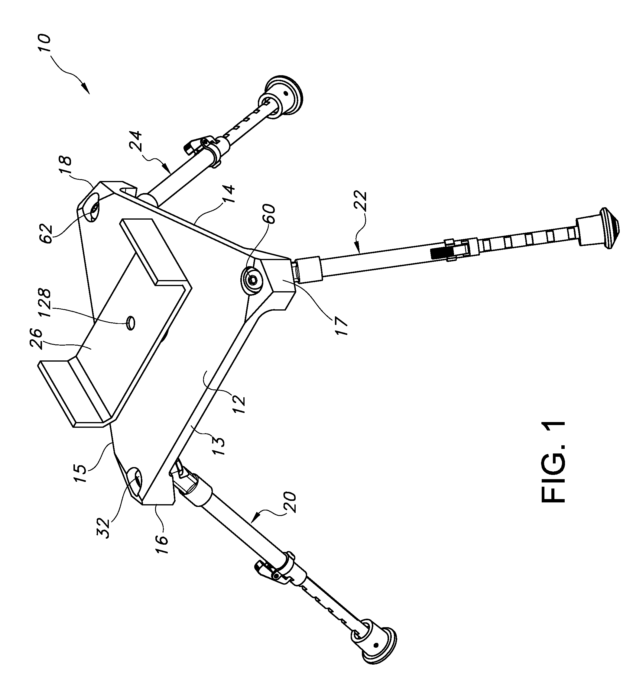
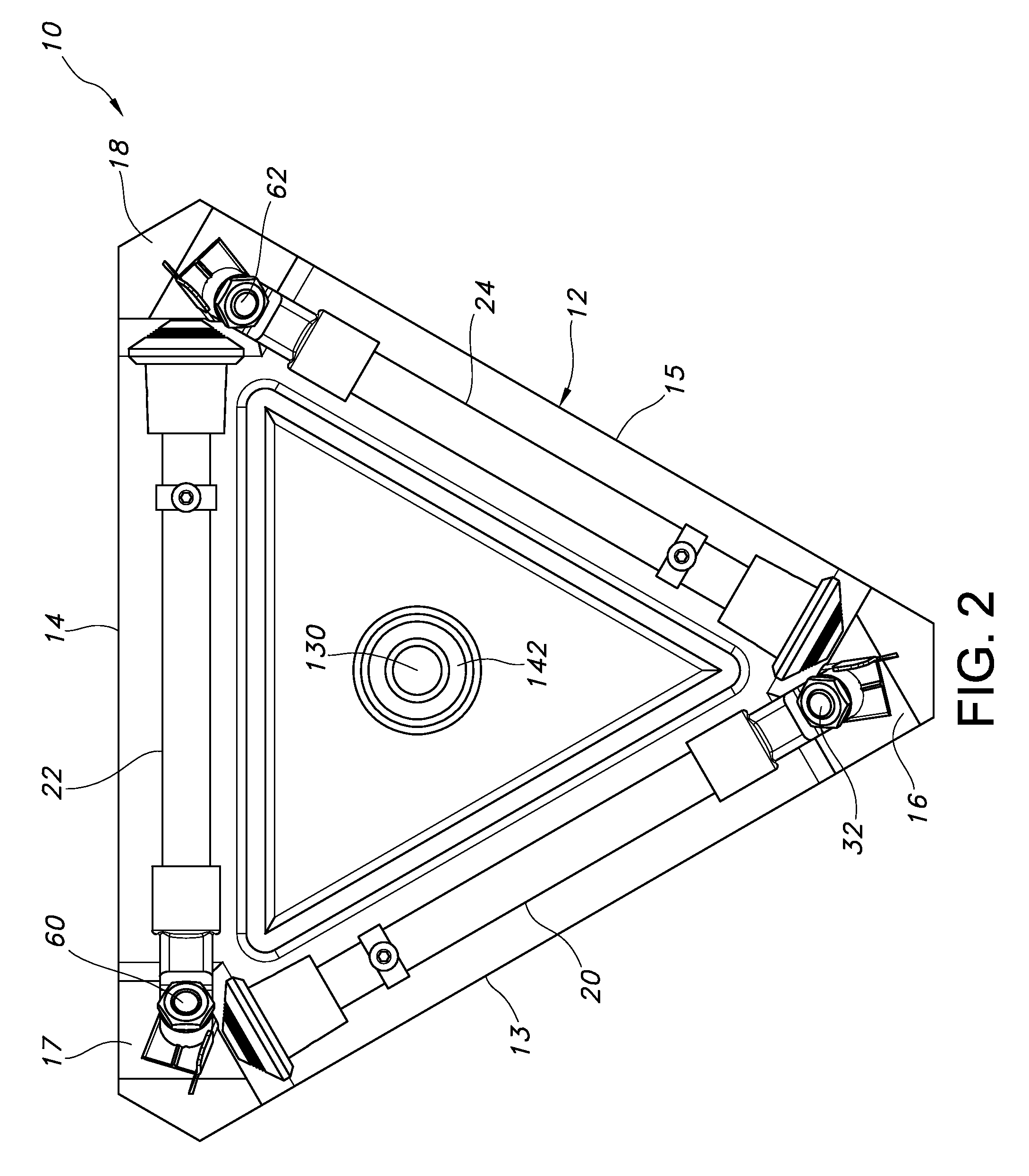
[0034]Turning now to a more detailed description of the invention, FIGS. 1-20 illustrate a tripod assembly 10 which incorporates a polygonal, planar top support plate, or base 12 having three sides 13, 14 and 15, preferably of substantially equal length to form a triangular support. The three sides converge to meet at truncated corners, or vertices, to form three downwardly extending shoulders 16, 17, and 18 to which are hingedly attached three corresponding support legs 20, 22, and 24.

[0035]As illustrated in FIG. 1, accessory kit 26, here shown as a bench rest type mount, is secured to the top of the tripod assembly base, as will be described in greater detail hereinbelow. Each of the support legs 22 and 24 are substantially identical to leg 20, which is illustrated in FIG. 4 as being connected to an inner, downwardly and outwardly sloping surface 30 of shoulder 16 by a pivot pin 32 having a head 34 and a shaft 36 that extends through a Belleville spring washer 38, a bore 40 in the...


PUM

PropertyMeasurementUnit
Lengthaaaaaaaaaa

Abstract

A tripod assembly having multiple interchangeable accessories for use in supporting a firearm or other device includes mounting couplers for releasably securing the assembly to an attachment point on a device to be supported, such as the forearm of a rifle, mounting brackets that are not affixed to the device to be supported, and threaded fasteners adapted for connection to standard threaded sockets for supporting devices such as cameras, spotting scopes and the like. The tripod assembly has a substantially planar, generally triangular tripod base including three sides terminating in, and defining, first, second and third vertices carrying respective first, second and third telescoping support legs.

Description

RELATED PATENT AND PENDING PATENT APPLICATION INFORMATION[0001]This application claims the benefit of U.S. Provisional Application No. 61 / 193,960, filed Jan. 13, 2009, the entire disclosure of which is hereby incorporated herein by reference, and is owned by the applicant / owner of U.S. Pat. No. 5,711,103, U.S. Pat. No. 5,815,974, and U.S. Pat. No. 7,631,455, the entire disclosures of which are hereby incorporated herein by reference.FIELD OF THE INVENTION[0002]The present invention relates, in general, to a method of supporting a device such as a firearm on a surface for steadying the supported device, and to support devices such as table top supports. More particularly, the invention relates to an apparatus useful as a firearm support accessory and to a method of supporting a firearm. In one form of the invention, a clamp assembly is utilized to attach the firearm support accessory to a mounting structure that is affixed to the forearm stock of a firearm. The clamp assembly is remo...

Claims


Application Information

Patent Timeline
IPC IPC(8): F41A23/14B23P11/00
CPCF16B7/105F16M11/32F41A23/14F16M11/08Y10T29/49826F16M11/16F16M11/36F16M2200/028F16M11/10
Inventor KENG, DA
Owner KENGS FIREARMS SPECIALTY
Why Eureka
Try Eureka