Scanning System for Scanning an Object Surface, in Particular for a Coordinates Measurement Machine

a scanning system and object technology, applied in the field of coordinates measurement machines, can solve the problems of high cost, low scanning speed, and significant connection of the required contact with the measuring obj

Inactive Publication Date: 2010-09-02
ISIS SENTRONICS
View PDF7 Cites 13 Cited by
  • Summary
  • Abstract
  • Description
  • Claims
  • Application Information

AI Technical Summary

Benefits of technology

[0021]In a third operating state, the piezoelectric excitation of the transport elements is shut off. In this state, the friction between the transport elements and the external wall of the bearing section prevents unintentional changes of the position of the light transport module. The drive is thus self-locking.

Problems solved by technology

With high effort, very good precision down into the sub-μm range can be achieved with mechanical scanners, but the required contact with the measuring objects is connected with significant disadvantages.
On one hand the scanning speed is low and thus the total measuring time is high, and on the other hand damage or measurement value deviations are unavoidable on sensitive or elastic surfaces.
However, this technology is only suitable for specific objects and requires large and complex sensors.

Method used


Image

  • Scanning System for Scanning an Object Surface, in Particular for a Coordinates Measurement Machine
  • Scanning System for Scanning an Object Surface, in Particular for a Coordinates Measurement Machine
  • Scanning System for Scanning an Object Surface, in Particular for a Coordinates Measurement Machine

Examples


Embodiment Construction

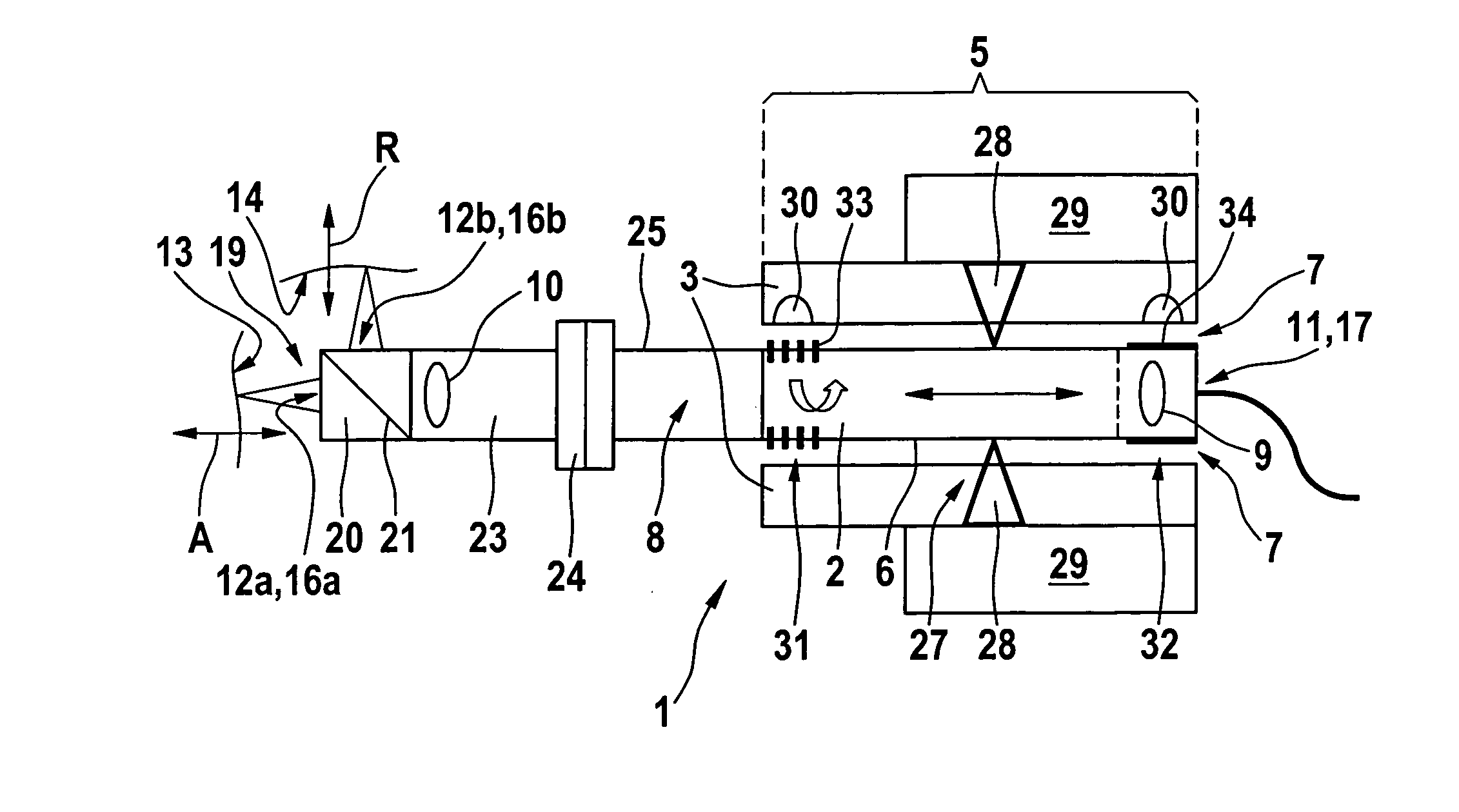
[0035]The scan sensor 1 shown in FIG. 1 comprises an elongate light transport module 2, which is air-mounted by means of a bearing part 3. The light transport module 2 is enclosed, at least in a bearing section 5, by a cylindrical external wall 6, which is in turn enclosed by the bearing part 3 in such a manner that a bearing gap 7 is present therebetween. Air is pressed into the gap by a compressed air source (not shown). Of course, the designs of the bearing section 5 and of the bearing part 3 as well as the pressure of the air pressed into the air gap 7 must be adapted to one another in such a manner that the light transport module 2 is mounted contactlessly within the entire desired movement range and at any load occurring in operation. It is in principle sufficient if the light transport module 2 has one or more cylindrical bearing sections extending a relatively short distance in the axial direction, provided their length is sufficient to ensure the desired axial mobility. How...


PUM


Abstract

Scanning system for scanning the surface (13, 14) of an object, in particular for a coordinates measurement machine. A scan sensor (1) comprises at least one fluid-mounted light transport module (2), a fluid being located between the light transport module (2) and a bearing part (3) in a bearing gap (7), by means of which fluid the light transport module (2) is mounted in such a manner that it is movable both axially and also rotating in relation to the axis of the cylindrical external wall. Primary light originating from a light source is transported through the interior (8) of the light transport module (2) to a primary exit point (12a, 12b) distal in the axial direction, from which it is emitted in the direction toward the object surface (13, 14). Secondary light reflected from the object surface (13, 14) is also transported through the interior (8) of the light transport module (2) to a secondary light exit point (17) distal in the axial direction from the secondary light entry point (16a, 16b). The light transport module is drivable both in the axial direction and also rotating by means of a rotation-translation drive (27).

Description

[0001]Numerous fields of application require high precision scanning of the surface of an object. The term “to scan” is generally to be understood as referring to any method in which a plurality of measuring points are detected on a surface to obtain information about its shape in space. In particular, the determination of the exact dimensions of an object (“dimensional examination”) is important, but also determination of the structural properties of the surface, i.e., its roughness, for example.[0002]The scanning system according to the invention is in particular suitable as a so-called “scan sensor” for coordinates measurement machines, which are used, for example, in industrial manufacturing operations, but also in laboratories for dimensional examination, including detecting surface structures and structural defects. Such coordinates measurement machines have a multidimensional high-precision drive, by means of which a scan sensor is moved in relation to the examined object whi...

Claims


Application Information

Patent Timeline
Patent Type & Authority Applications(United States)
IPC IPC(8): H04N1/04
CPCG01B11/007G01B11/24G01B11/03
Inventor KNUTTEL, ALEXANDER
Owner ISIS SENTRONICS
Why Eureka
Try Eureka