
Apparatus for receiving and transferring kinetic energy from water flow

a technology of fluid basins and apparatuses, which is applied in the direction of sea energy generation, motors, tidal streams/damless hydropower, etc., can solve the problem of needing a damping means for absorbing the shock energy of the blades, and achieve the effect of bigger kinetic energy

Inactive Publication Date: 2010-09-02
SHREIDER VLADIMIR ANATOL +1
View PDF33 Cites 6 Cited by
  • Summary
  • Abstract
  • Description
  • Claims
  • Application Information

AI Technical Summary

Benefits of technology

"The present invention relates to an apparatus for generating energy from fluid flow using a tangential fluid turbine. The invention includes a controlling means for increasing the turning moment of the shaft by utilizing the kinetic energy of the fluid. The apparatus includes a hub with a plurality of elongate springs connected to the shaft and the blade, which can rotate between a lower working position and an upper position. The blade can rotate at different speeds to transfer the kinetic energy to the hub. The hub has a room for accommodating energy-generating parts and closed tanks for controlling buoyancy and balance. The invention also includes a controlling means for the blades, which can adjust the depth of sinking of the blades into the fluid and the magnitude of the kinetic energy received by the blades. The technical effects of the invention include increased energy generation and improved efficiency of the fluid turbine."

Problems solved by technology

WO 9961791 filed 1999 Dec. 2 that is provided with blades turnable by the flow through 180° between positions across and along the flow and has the disadvantage such as needing of a damping means for absorbing shock energy of the blades.

Method used


Image

  • Apparatus for receiving and transferring kinetic energy from water flow
  • Apparatus for receiving and transferring kinetic energy from water flow
  • Apparatus for receiving and transferring kinetic energy from water flow

Examples


first embodiment

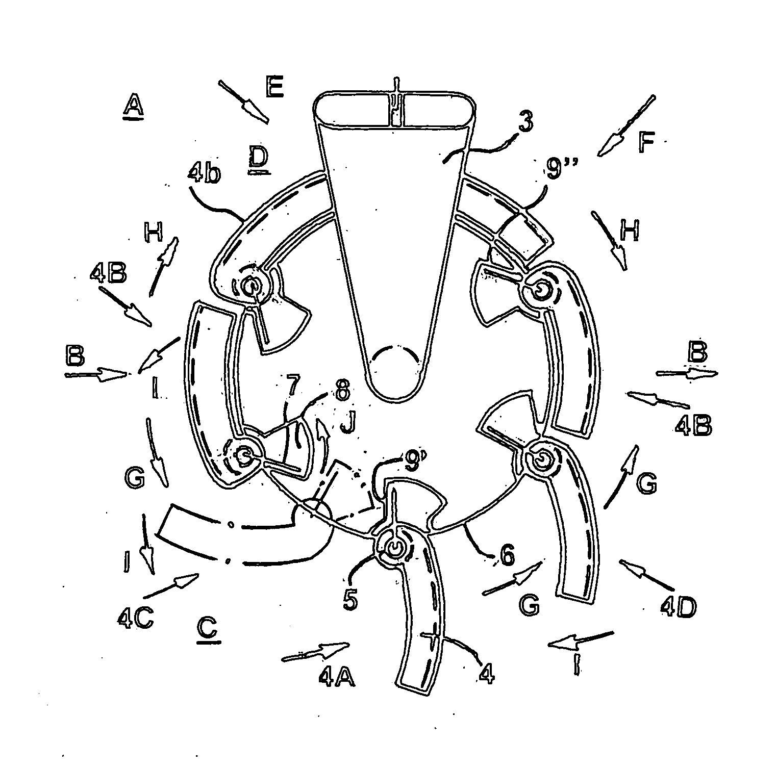
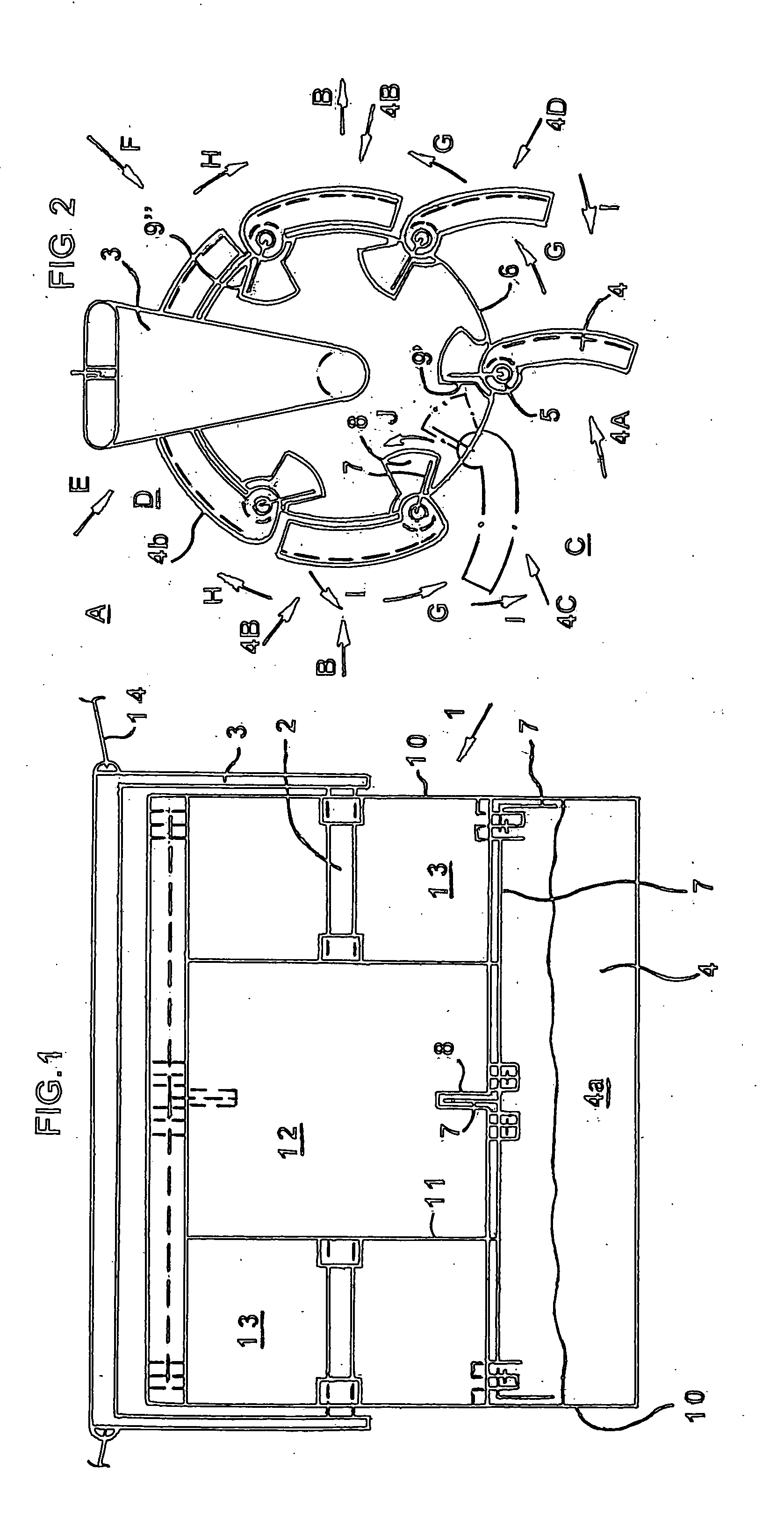
[0027]the turbine E as illustrated in FIGS. 1 and 2 is adapted to submerge and capable of being maintained in a path of the main flow A preferably water flowing in the direction B and comprises a relatively widened turbine runner F capable of facing, directing and speeding the flow C in a direction shown by an arrow G in FIG. 2 and having a runner hub 1 for supporting components of the runner F that is capable of rotating about a generally horizontal central axis of opposite axles 2 of a turbine frame shroud 3 capturing the runner F, the axis being disposed in general crossing alignment with the path of the flow A, and at least 3, preferably 6 axially extending, elongate, flow kinetic energy-receiving paddle or wing blades 4 distributed around and individually and turnably connected as at 5 by means of a plurality of bearing lugs and brackets or a piano bearing hinge connections and the like and pins that formed on the hub 1 remotely from the axis. The hinges 5 permit the blades 4 t...

second embodiment

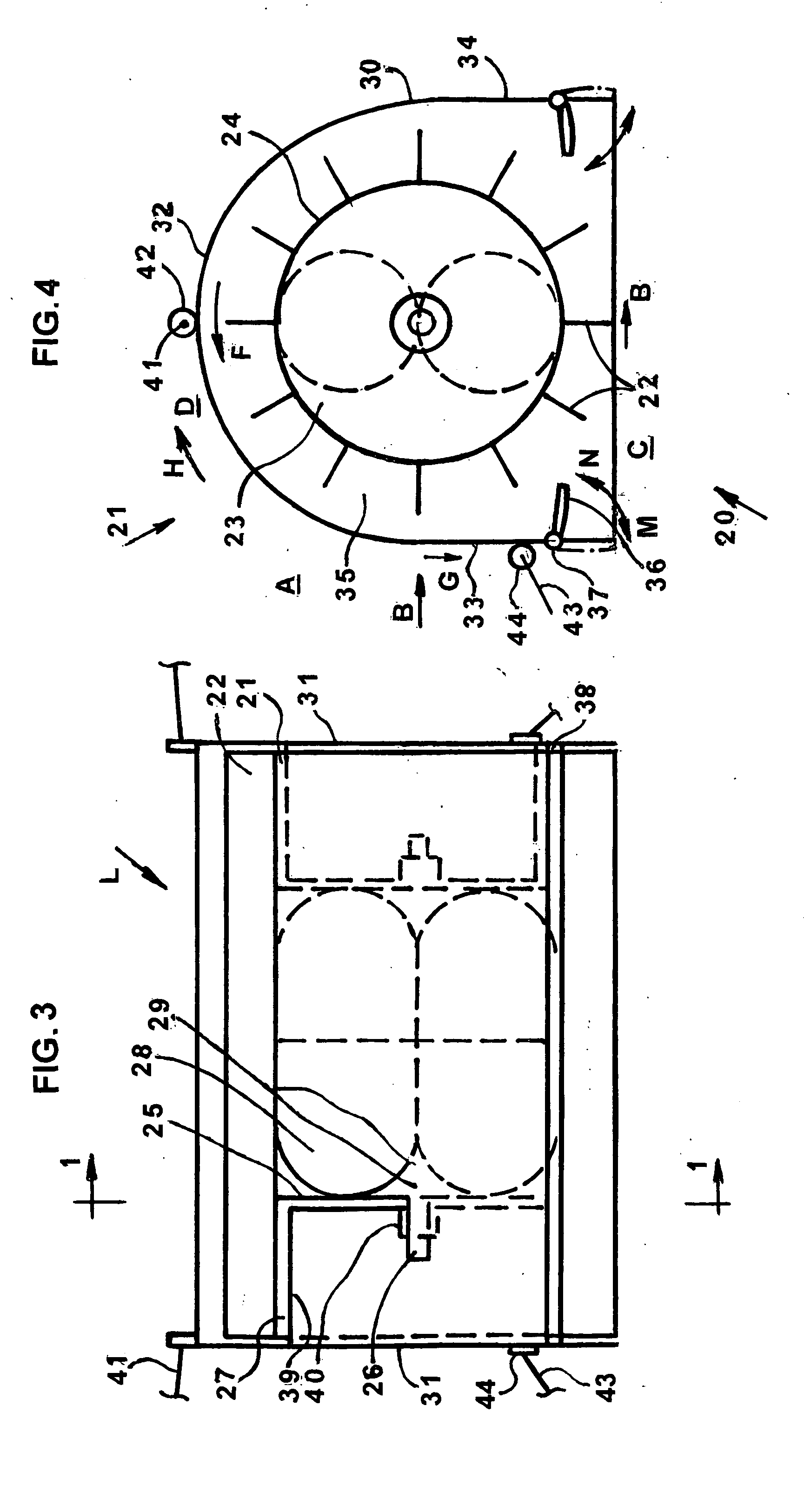
[0036]the invention is a tangential hydro-turbine L for receiving the kinetic energy of the flow A, preferably a river or a sea current in the direction B, that is adapted to submerge in the water flow A and composed of a turbine runner 20 as shown in FIGS. 3 and 4 and a turbine shroud 21 capturing the runner 20. The runner 20 comprises a set or a plurality of parallel and radial blades or paddles 22 generally arranged on a periphery of a runner hub 23 for rotation about a generally horizontal axis of the runner 20, the axis being across the direction B in FIG. 4. The hub 23 extends along the axis and serves to support and guide the blades 22 during their rotation in the direction B and comprises a co-axially disposed, circular cylindrical shell wall 24, circular disk-shaped inner walls 25 and opposite output shafts 26 fixed on the walls 25 in general transversal alignment with the direction B. The walls 24 and 25 define opposite pockets or recesses 27 for accommodating opposite sup...


PUM


Abstract

A tangential turbine is adapted for receiving kinetic energy from a flowing fluid and comprises a supporting shroud, a rotating runner having a hub and a plurality of radial blades spaced apart on the hub, and a means for controlling the receiving. In first embodiment the controlling means comprises a plurality of springs each connected with its ends turningly about a connecting axis being between and within the hub and the blade and between limit stops to the hub and fixedly to the blade turnable about the axis to a non-working tangential position. In second embodiment the controlling means comprises the shroud shaped into a caisson and provided with turnable aprons and capable of accommodating the runner in the air and controlling the insertion of the blades into the flow below the shroud.

Description

CROSS-REFERENCE TO RELATED APPLICATIONS[0001]This application is a continued-in-part application / Control Number Ser. No. 12 / 001,943, Art Unit 2839, filed Dec. 14, 2007 and non-elected and withdrawn from consideration pursuant to 37 CFR 1.142 (b)STATEMENT REGARDING FEDERAL SPONSORED R and D[0002]Not ApplicableREFERENCE TO A MICROFICHE APPENDIX[0003]Not applicableBACKGROUND OF THE INVENTION[0004]The invention relates to apparatuses for receiving and transferring kinetic energy of a fluid basin, especially a water basin into any usable power and especially to submersible tangential fluid and hydro-turbines as defined in claim 1.[0005]There exists a need for effective, high-speed hydro-turbines which do not require substantial vehicular support for deployment or retrieval and can be placed in a particular optimal operative position in a path of a water flow, then easily manoeuvred to a different position within the flow in the event of a change of location of the optimal path and stabil...

Claims


Application Information

Patent Timeline
Patent Type & Authority Applications(United States)
IPC IPC(8): F01D1/02
CPCY02E10/28F03B17/065Y02E10/30Y02E10/20
Inventor SHREIDER, VLADIMIR ANATOLSHREIDER, NATALIIA
Owner SHREIDER VLADIMIR ANATOL
Learn More