Turbocharger engine

a turbocharger and engine technology, applied in the direction of machines/engines, liquid fuel engines, mechanical equipment, etc., can solve the problems of loss of kinetic energy for driving a turbine, complicated structure of the exhaust passage communicating between the two turbine chambers, etc., and achieve the effect of large kinetic energy

Active Publication Date: 2020-09-01
MAZDA MOTOR CORP
View PDF25 Cites 0 Cited by
  • Summary
  • Abstract
  • Description
  • Claims
  • Application Information

AI Technical Summary

Benefits of technology

[0005]An object of the present invention is to provide a turbocharger engine provided with a turbocharger including two independent turbo units, which enables to give large kinetic energy from exhaust air to turbines, and to attain miniaturization.

Problems solved by technology

In the aforementioned dual stage turbocharger, the structure of an exhaust passage, particularly, the structure of an intra-turbine exhaust passage communicating between two turbine chambers tends to be complicated.
This may cause a resistance against a flow of exhaust air in the exhaust passage, and kinetic energy for driving a turbine may be lost.
Therefore, satisfying the aforementioned two demands at a high level is a challenging task.

Method used


Image

  • Turbocharger engine
  • Turbocharger engine
  • Turbocharger engine

Examples


Embodiment Construction

Schematic Configuration of Engine

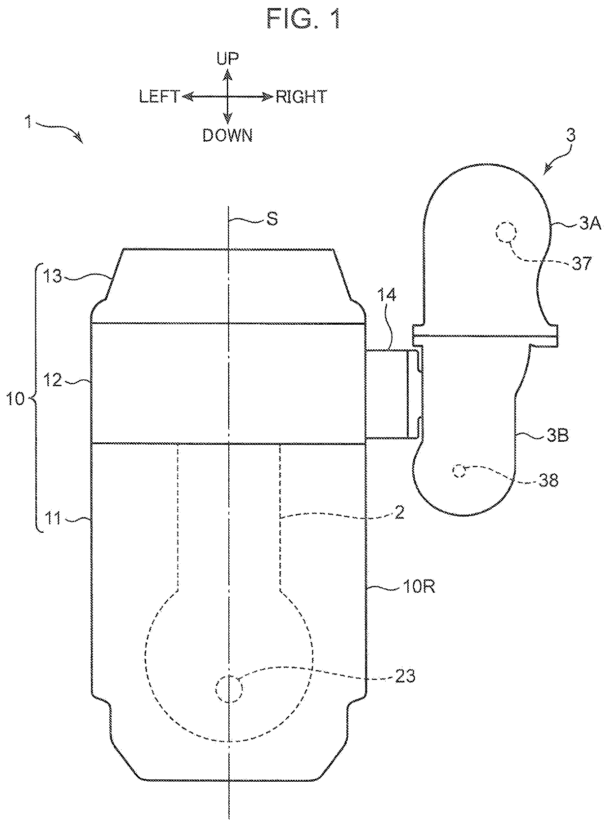
[0019]In the following, a turbocharger engine according to an embodiment of the present invention is described in detail based on the drawings. First of all, a schematic configuration of the engine is described. FIG. 1 is a perspective view of a turbocharger engine 1 according to the embodiment of the present invention. In FIG. 1 and the other drawings, a front direction, a rear direction, a left direction, a right direction, an upper direction, and a lower direction are indicated. This is for the sake of explanation, and does not necessarily indicate actual directions.

[0020]The turbocharger engine 1 includes a multi-cylinder engine body 10, an exhaust manifold 14 connected to a right surface 10R of the engine body 10, an unillustrated intake manifold, and a turbocharger 3 disposed adjacent to the right side of the engine body 10. Although illustration is omitted in FIG. 1, the periphery of the exhaust manifold 14 is surrounded by a manifold insulato...


PUM


Abstract

A turbocharger engine includes a dual stage turbocharger in which a first turbo unit is disposed on the upstream side of a second turbo unit on an exhaust passage. The turbocharger is disposed in such a manner that a second turbine shaft of the second turbo unit is far from an engine output shaft than a first turbine shaft of the first turbo unit in a plan view in an axis direction of a cylinder. Further, a second turbine is rotated clockwise around an axis thereof in a side view when the turbocharger is viewed from the side of the turbine, and an intra-turbine passage is disposed on the side of an engine body than the second turbine shaft.

Description

TECHNICAL FIELD[0001]The present invention relates to a turbocharger engine provided with a turbocharger including two independent turbo units in an engine body.BACKGROUND ART[0002]In a turbocharger engine, a turbocharger configured to supercharge intake air by using exhaust energy of an engine is mounted adjacent to a side wall of an engine body. An exhaust passage and an intake passage are formed in a housing of the turbocharger. A turbine chamber configured to accommodate a turbine communicates with the exhaust passage. A compressor chamber configured to accommodate a compressor impeller communicates with the intake passage. Exhaust air is supplied to the exhaust passage from the engine body, and intake air to be supplied to the engine body flows through the intake passage. The turbine is rotated around a turbine shaft by exhaust air to rotate the compressor impeller in the compressor chamber, which is connected to the turbine shaft to supercharge intake air.[0003]Conventionally,...

Claims


Application Information

Patent Timeline
Patent Type & Authority Patents(United States)
IPC IPC(8): F02B37/00F04D25/04F02B37/18F04D17/14F04D29/42F02B37/013F04D17/12
CPCF04D25/04F04D17/127F02B37/18F04D17/14F04D29/4206F02B37/004F02B37/013Y02T10/12F02B37/002
Inventor NIWA, YASUSHIUEHANE, YOSHIYUKIARAKI, KEIJI
Owner MAZDA MOTOR CORP
Why Eureka
Try Eureka