Hermetic compressor

a compressor and hermetic technology, applied in the direction of positive displacement liquid engines, piston pumps, lighting and heating apparatuses, etc., can solve the problems of increasing input power and abrasion wear, and achieve the effects of reducing the frequency of sliding, high efficiency and high reliability

Inactive Publication Date: 2010-09-02
PANASONIC CORP
View PDF4 Cites 3 Cited by
  • Summary
  • Abstract
  • Description
  • Claims
  • Application Information

AI Technical Summary

Benefits of technology

[0024]Since the structure devised as above makes the plurality of balls roll along two or more separate tracks on rolling surfaces of the upper and lower races, the number of the balls that roll on each track is decreased, thereby reducing substantially the frequency of sliding betw

Problems solved by technology

For this reason, when the operating time is prolonged, a frequency of sliding between balls 60 and tracks 74a, 74b increases excessively, thereby increasing abrasion wear.
This results i

Method used


Image

  • Hermetic compressor
  • Hermetic compressor
  • Hermetic compressor

Examples


first exemplary embodiment

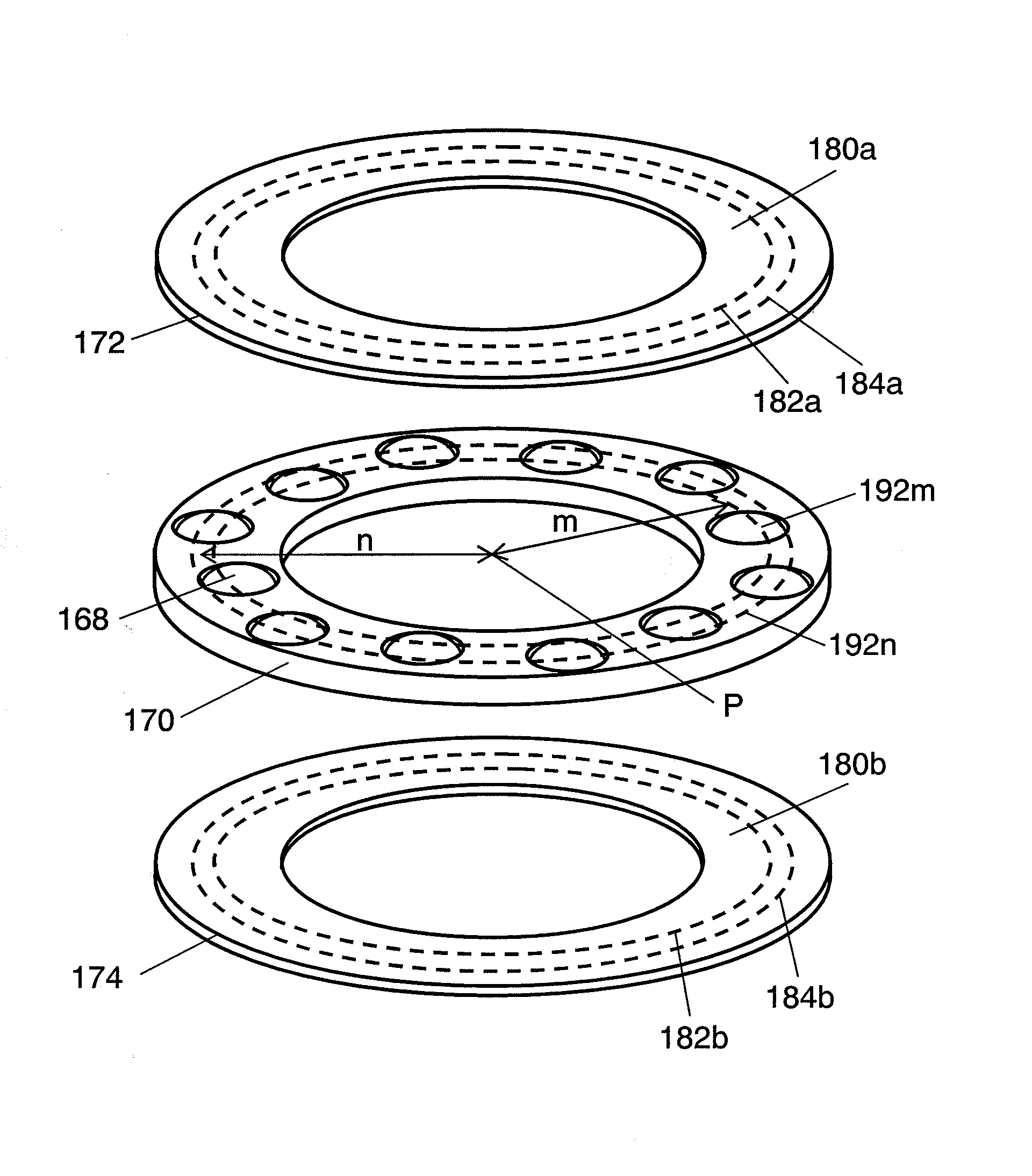
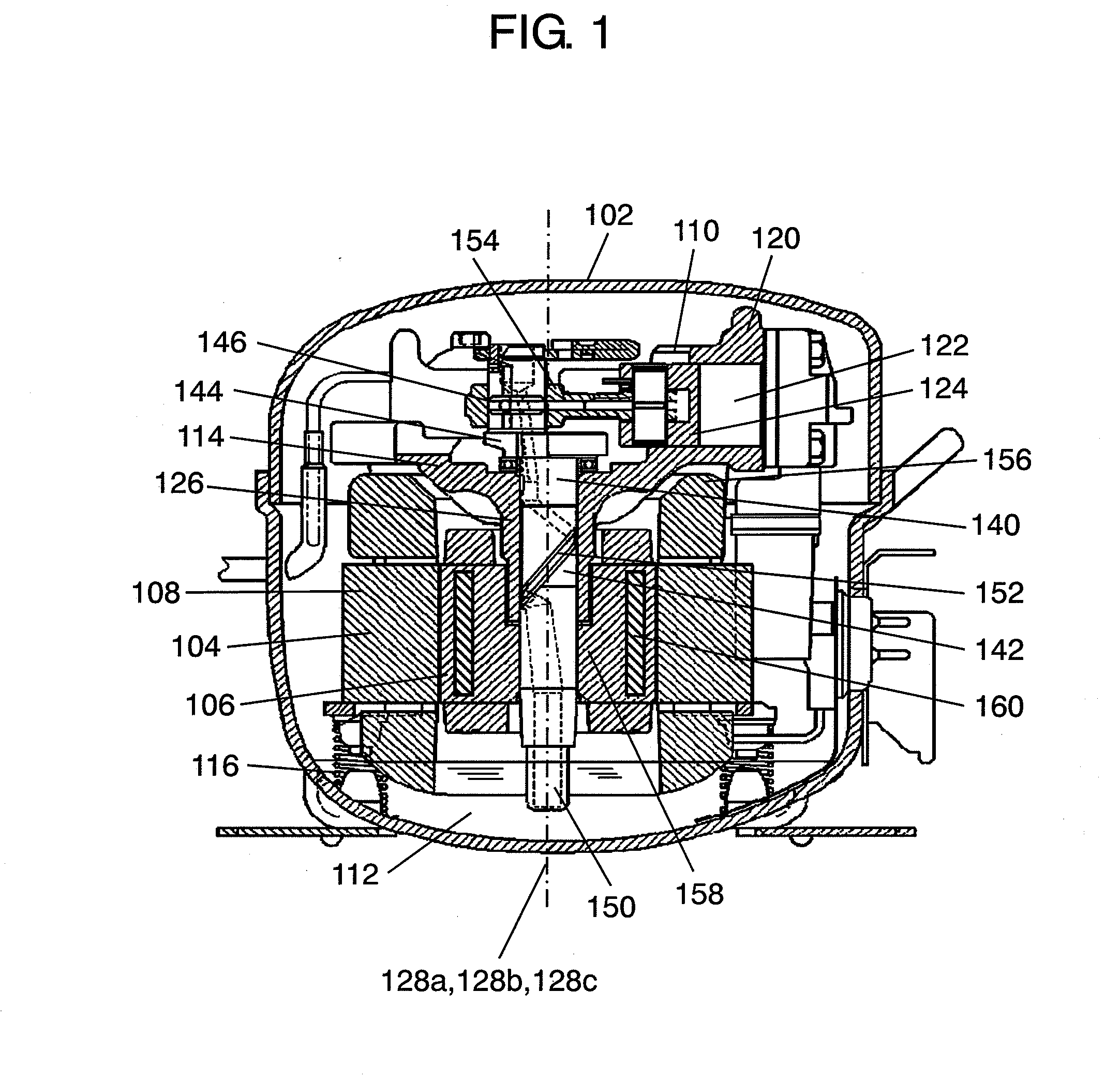
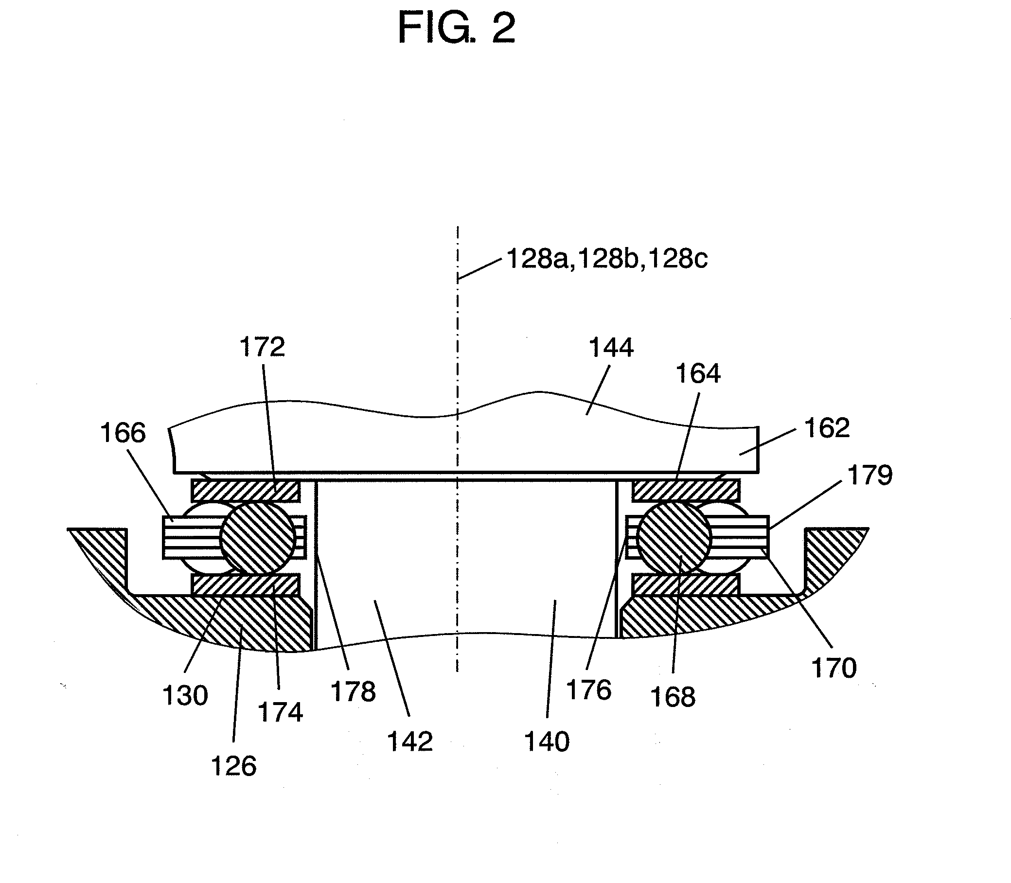
[0035]FIG. 1 is a vertical cross-sectional view of a hermetic compressor according to the first exemplary embodiment of the present invention, FIG. 2 is an enlarged view of an essential portion of the hermetic compressor of FIG. 1, and FIG. 3 is a perspective view of a thrust-ball bearing of this exemplary embodiment.

[0036]In FIG. 1 to FIG. 3, hermetically sealed container 102 houses motor element 108 formed of stator 104 and rotor 106 driven by an inverter power supply unit (not shown), compressor element 110 driven in a rotary motion by motor element 108, and lubricating oil 112 of low viscosity having a viscosity grade of VG5 stored in a bottom part thereof.

[0037]Motor element 108 and compressor element 110 are assembled into one unit to compose compressor mechanism 114. This compressor mechanism 114 is resiliently supported by a plurality of coil springs 116 within hermetically sealed container 102.

[0038]Description of the main structure of compressor element 110 is provided nex...

second exemplary embodiment

[0068]FIG. 4 is a vertical cross-sectional view of a hermetic compressor according to the second exemplary embodiment of this invention, FIG. 5 is an enlarged view of an essential portion of the hermetic compressor shown in FIG. 4, and FIG. 6 is a perspective view of a thrust-ball bearing of this exemplary embodiment.

[0069]In FIG. 4 to FIG. 6, hermetically sealed container 202 houses motor element 208 formed of stator 204 and rotor 206 driven by an inverter power supply unit (not shown), compressor element 210 driven in a rotary motion by motor element 208, and lubricating oil 212 of low viscosity having a viscosity grade of VG5 stored in a bottom part thereof.

[0070]Motor element 208 and compressor element 210 are assembled into one unit to compose compressor mechanism 214. This compressor mechanism 214 is resiliently supported by a plurality of coil springs (not shown) within hermetically sealed container 202.

[0071]Description of the main structure of compressor element 210 is prov...


PUM


Abstract

A hermetic compressor of the present invention includes a thrust-ball bearing having balls (168) disposed in a holder (170) in a manner that the balls (168) roll along at least two tracks (182a, 182b, 184a and 184b). The invented structure decreases the number of balls (168) that roll along each of the tracks (182a, 182b, 184a and 184b), and reduces a frequency of sliding between the balls (168) and the tracks (182a, 182b, 184a and 184b), thereby alleviating wear of the tracks.

Description

TECHNICAL FIELD[0001]The present invention relates to hermetic compressors used for appliances such as refrigerators and freezers.BACKGROUND ART[0002]There is a strong demand in recent years for high efficiency for reduction of power consumption, as well as low noise and high reliability of hermetic compressors used for refrigeration apparatuses such as refrigerators and freezers.[0003]Typical hermetic compressors of this kind hitherto available have a structure provided with a thrust-ball bearing to make a shaft freely rotatable about a main axis bearing for the purpose of improving the efficiency (refer to patent document 1 for example).[0004]Description is provided hereinafter of the conventional hermetic compressor noted above with reference to the drawings.[0005]FIG. 7 is a vertical cross-sectional view of the conventional hermetic compressor described in patent document 1, FIG. 8 is an enlarged view of an essential portion shown in FIG. 7, and FIG. 9 is a perspective view of a...

Claims


Application Information

Patent Timeline
IPC IPC(8): F04B39/02F04B35/04F16C19/10F16C35/06
CPCF04B39/0215F16C19/10F04B39/0246F04B35/04F25B31/00F05B2240/50Y10S384/00Y10S417/902
Inventor YANASE, SEIGO
Owner PANASONIC CORP
Why Eureka
Try Eureka