Garment Protective Assembly

a protective assembly and garment technology, applied in the field of protective clothing, can solve the problems of limiting mobility, uncomfortable tight elastic straps, joint injuries, etc., and achieve the effect of facilitating air flow and less restrictive movement of the wearer

Active Publication Date: 2010-09-09
LINEWEIGHT
View PDF27 Cites 10 Cited by
  • Summary
  • Abstract
  • Description
  • Claims
  • Application Information

AI Technical Summary

Benefits of technology

[0012]It is an object of the present invention to provide a garment protective assembly which is less restrictive of the wearer's movements.
[0013]It is another object of the present invention to provide a garment protective assembly which facilitates air flow to the protected joint.
[0014]It is a further object of the present invention to provide a garment protective assembly configured for wearer comfort.

Problems solved by technology

Moreover, it is sometimes necessary to assume these positions rapidly or unexpectedly.
Certain sporting and leisure activities can also lead to joint injuries if precautions are not taken.
However, the tight elastic straps can be uncomfortable or can limit mobility.
Moreover, the close-fitting pads can be especially hot during extended wear.
In addition, the independent pads can be difficult to combine with other necessary garments, such as coveralls, fatigues, or jumpsuits, as the padding may, when used in combination with such clothing, restrict movement and ventilation and interfere with the garment.
Furthermore, the hard shell of an independent pad, if worn interior to the garment, can result in the shredding or abrasion of the garment itself, which is caught between the hard shell of the pad and the hard exterior objects.
If worn exterior to the garment, the pad can be excessively restrictive of the movement of the garment, and impair the mobility of the wearer.
Some garments have pockets into which the foam pad is inserted, but if the hard shell is also inserted into this type of pocket, it would no longer provide protection for the garment fabric.

Method used


Image

  • Garment Protective Assembly
  • Garment Protective Assembly
  • Garment Protective Assembly

Examples


Embodiment Construction

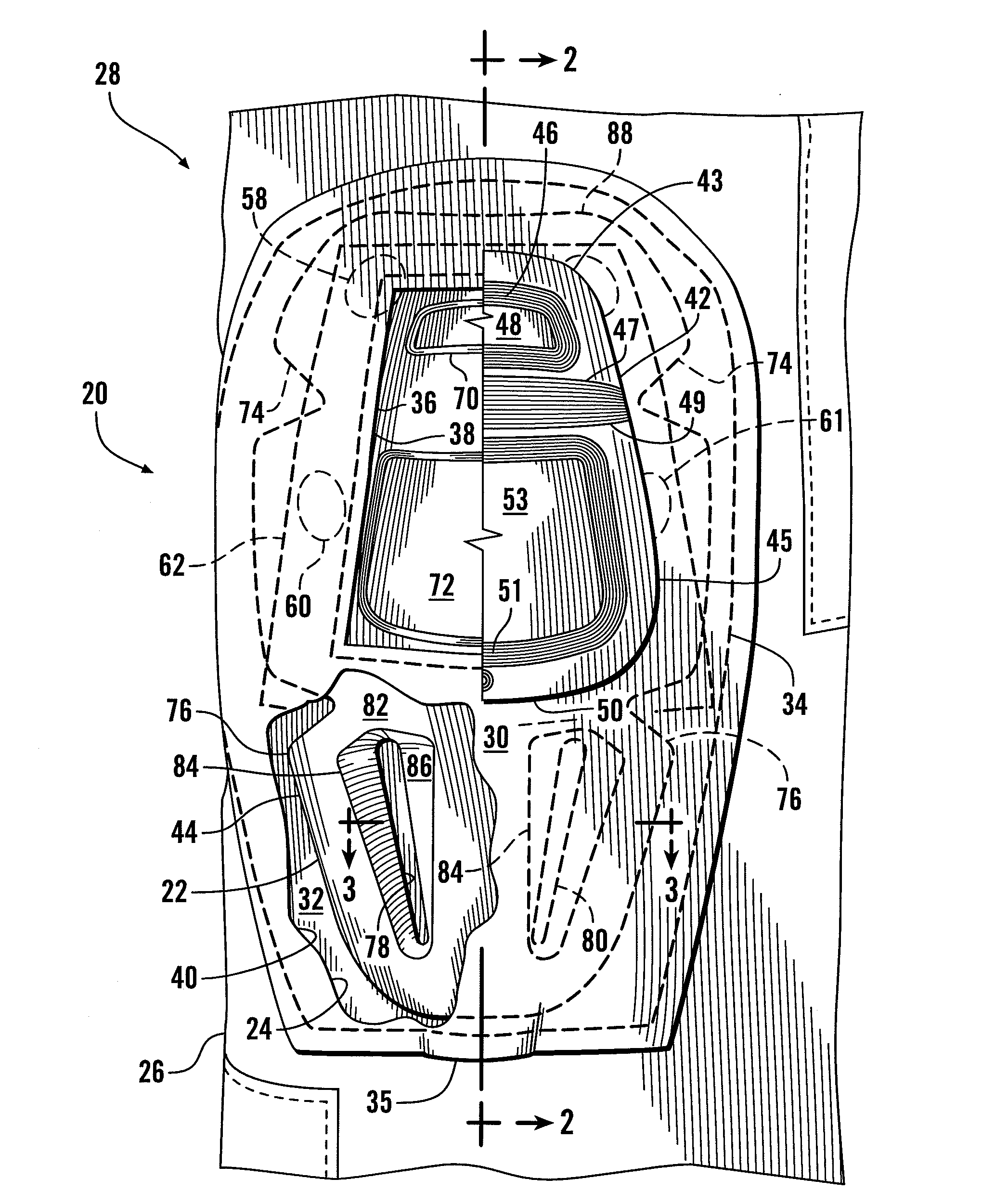
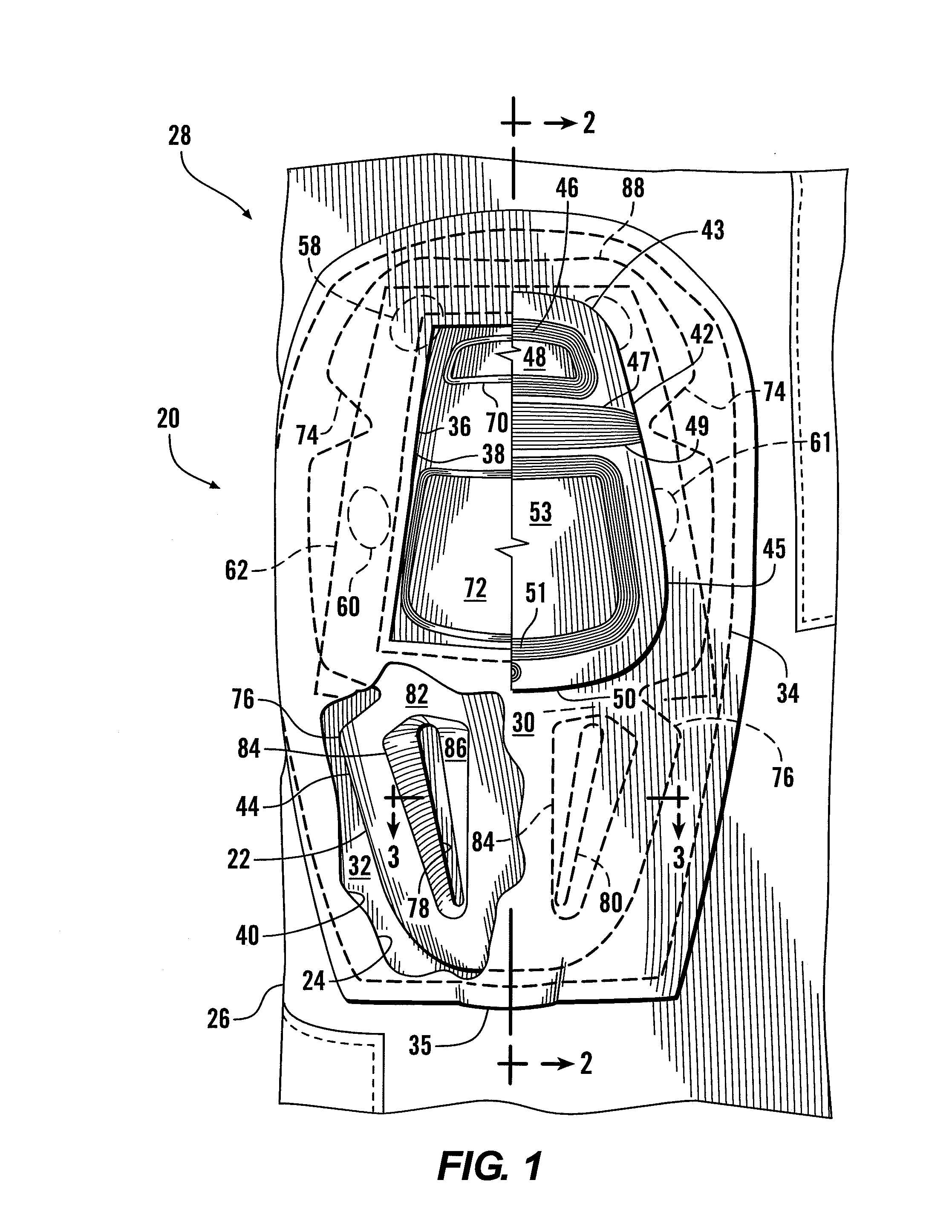
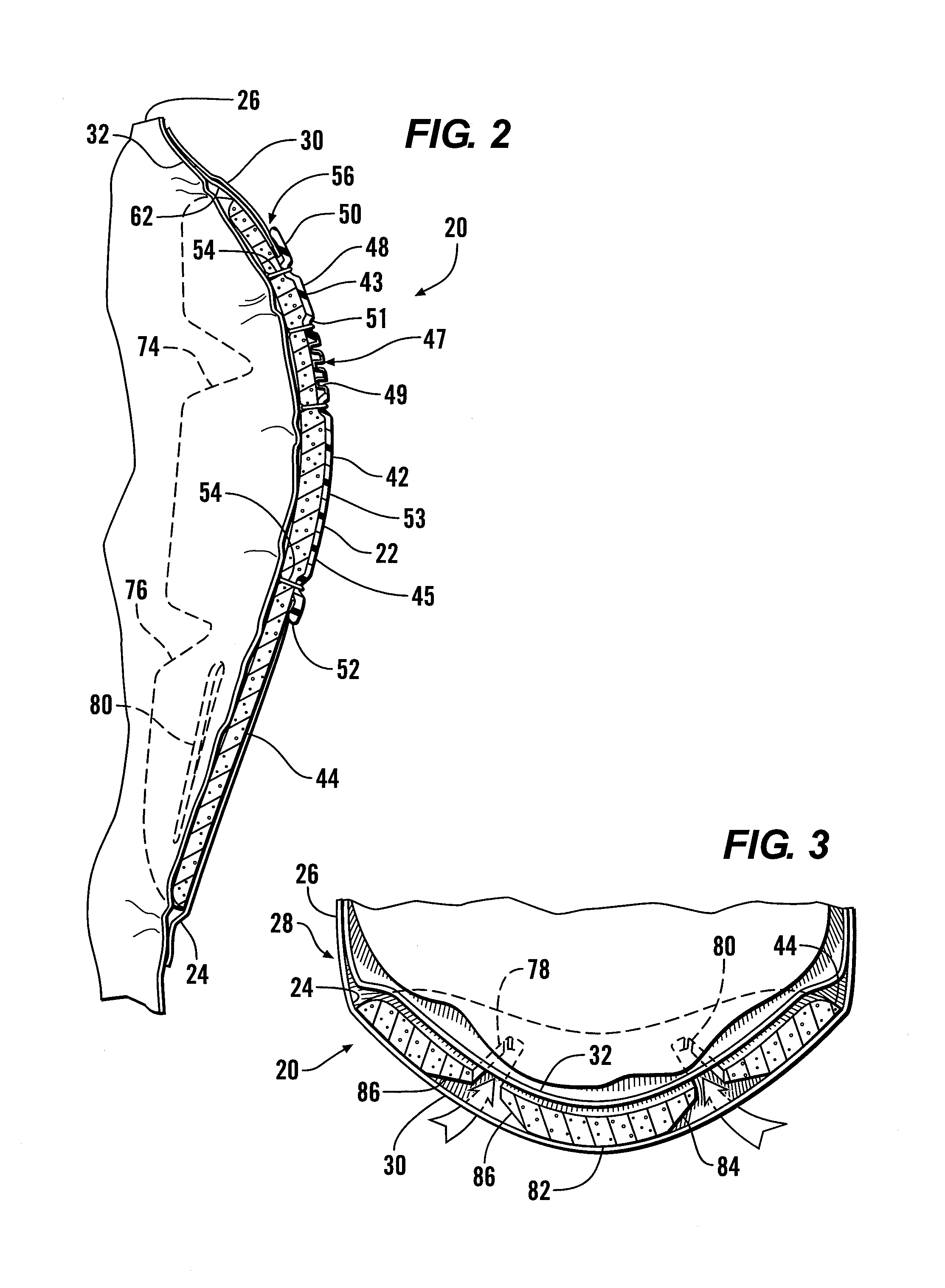
[0021]Referring more particularly to FIGS. 1-5, wherein like numbers refer to similar parts, a protective pad assembly 20 is shown in FIGS. 1-4. The protective pad assembly 20 is comprised of a protective element 22, and a pocket 24 formed on a pants leg 26 of a garment 28, for example a soldier's fatigues. The protective element 22 is symmetrical about a vertical axis, and has a cap 42 attached to an insert 44. In FIG. 1, the cap 42 is shown broken away generally about the vertical axis. The pocket 24 is accessible through a central opening 36, and is not open at the top or sides as in a common pocket. Other pocket configurations may be employed, such as the ones shown in U.S. Pat. No. 7,237,270, the disclosure of which is incorporated by reference herein. As shown in FIG. 2, the pocket 24 is defined between a fabric front layer 30 and a frontwardly facing fabric substrate 32 of the garment 28. The protective pad assembly illustrated is a knee pad assembly, but a similar arrangemen...


PUM


Abstract

A garment such as a shirt or pants has a front layer with portions which define a central opening defined by an inner periphery and positionable to overlie a portion of the joint to be protected such as a knee or an elbow. A removable protective insert is larger than the central opening and has a unitary cap sewn thereto. The cap has an upper segment separated from a lower segment by a bending joint defined by at least one groove which extends substantially across the cap. The upper segment and the lower segment are separately fixed to the protective insert by stitching. The upper segment and the lower segment have an outwardly projecting flange which overlies the protective insert, the flange having portions which engage the front layer of the garment between the cap flange and the protective insert. A slot in the insert ventilates through the front layer.

Description

CROSS REFERENCES TO RELATED APPLICATIONS[0001]This application claims the benefit of U.S. provisional app. No. 61 / 149,960, filed Feb. 4, 2009, the disclosure of which is incorporated by reference herein.STATEMENT AS TO RIGHTS TO INVENTIONS MADE UNDER FEDERALLY SPONSORED RESEARCH AND DEVELOPMENT[0002]Not applicable.BACKGROUND OF THE INVENTION[0003]The present invention relates to protective clothing in general, and more particularly to garments which incorporate pads for protection of the wearer's joints such as elbows and knees.[0004]There are many activities which require practitioners to take on cramped or reduced postures, such as crouching, crawling or lying prone, either momentarily or for extended periods. Moreover, it is sometimes necessary to assume these positions rapidly or unexpectedly. Kneeling and crawling, or collapsing to the knees, can be particularly injurious to the knees, either as a result of abrasion in the form of scraping, cutting, or puncturing, or as a resul...

Claims


Application Information

Patent Timeline
Patent Type & Authority Applications(United States)
IPC IPC(8): A41D13/05A41D13/06
CPCA41D13/065A41D13/0581
Inventor CRYE, CALEB CLARK
Owner LINEWEIGHT
Why Eureka
Try Eureka