Method and apparatus for laser beam processing of an element with total transmission for light of a t least 10-5

Active Publication Date: 2010-09-09
FLISOM
View PDF4 Cites 15 Cited by
  • Summary
  • Abstract
  • Description
  • Claims
  • Application Information

AI Technical Summary

Benefits of technology

[0021]The alignment mark is clearly visible in the acquired image because the contrast is significantly increased due to the positioning of the illumination unit on the other side of the element to be processed with respect to t

Problems solved by technology

Due to temperature and long term drift of the scanning mirrors the lateral precision is limited.
In case a to-be-processed element has a low mechanical stability, like foils, it is even more difficult to exactly establish the position of the laser beam relative to structures from an earlier processing step.
Therefore, a to-be-processed element having a low contrast, i.e. an element comprising layers with a light transmission ratio (total transmittance) below 10

Method used


Image

  • Method and apparatus for laser beam processing of an element with total transmission for light of a t least 10-5
  • Method and apparatus for laser beam processing of an element with total transmission for light of a t least 10-5
  • Method and apparatus for laser beam processing of an element with total transmission for light of a t least 10-5

Examples


Embodiment Construction

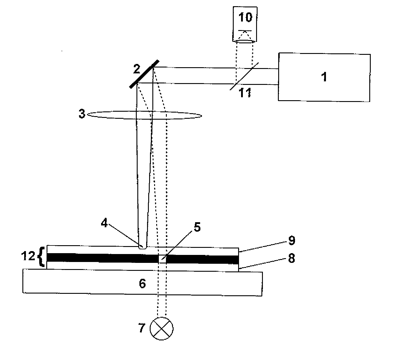
[0072]A first embodiment of an apparatus according to the present invention is schematically depicted in FIG. 1. The inventive apparatus comprises a laser unit 1, a scanning unit 2 with two galvanometer driven mirrors (for clarity only one mirror is shown in FIG. 1) to scan the beam of the laser unit 1 across a to-be-processed element 12, an focusing optic 3, an imaging system 10, a separation unit 11 and a illumination unit 7. The to-be-processed element 12 is supported by a mounting system 6, which is a plate for the embodiment depicted in FIG. 1.

[0073]It is pointed out that the term “scanning” is to be generally understood as a method to direct the impinging point of a light beam, which can be a laser beam or a light beam of an imaging system, for example, to any desired position within the area to be processed or inspected, preferably by the control of a computer. Therefore, different methods are possible. The scanning of the laser focus for laser processing can be either done b...


PUM

PropertyMeasurementUnit
Wavelengthaaaaaaaaaa

Abstract

A method and an apparatus for laser beam processing of an element (12) that has a total transmittance for light of at least 10−5, comprising a laser unit (1) for generating a laser beam on one side of the to-be-processed element (12), an illumination unit (7), an imaging system (10) comprising a sensor unit on the one side of the to-be-processed element (12), the sensor unit recording residual light that results from light of the illumination unit (7), a scanning unit (2) for adjusting the laser beam processing position, and a control unit. The control unit is operatively connected to the laser unit (1), the imaging system (10) and the scanning unit (2), and the illumination unit (7) is positioned on the other side of the to-be-processed element (12) in relation to the laser unit (1). Since the to-be-processed element (12) allows light to pass through an otherwise opaque or almost opaque layer, a good contrast is obtained that is used to determine the position of the laser beam with high precision.
Therefore, high precision laser processing is possible for materials with low transmission for light and low mechanical stability like flexible thin film solar cells.

Description

RELATED APPLICATION[0001]This application is a U.S. national phase application of International Application No. PCT / EP2007 / 057628 filed Jul. 24, 2007.TECHNICAL FIELD[0002]The present invention is related to a method for laser beam processing of an element as well as to an apparatus therefor.BACKGROUND AND SUMMARY[0003]A known method for laser beam processing of thin film solar cells is disclosed in WO 03 / 061 013 A1. A known method for laser beam processing for trimming a resistance, a reactance or a capacitance of a circuit board after each electronic component is mounted to the circuit board is disclosed in U.S. Pat. No. 5,670,068.[0004]In the known method for laser beam processing mentioned above, a laser beam is deflected by scanning mirrors and focused onto an element to be processed. Due to temperature and long term drift of the scanning mirrors the lateral precision is limited. The precision is further reduced, if large area substrates are used.[0005]In case a to-be-processed ...

Claims


Application Information

Patent Timeline
IPC IPC(8): B23K26/06B23K26/02
CPCB23K26/041H01L31/0475B23K26/0807B23K26/0846B23K26/0853B23K26/4085B23K2201/16B23K2201/18B23K2201/36B23K2203/16H01L31/0322H01L31/1864H01L31/1872H01L31/1884H05K1/0269H05K1/0393H05K3/0008H05K3/0026H05K2201/0108H05K2201/09918Y02E10/52B23K26/046B23K26/082B23K26/042B23K26/40Y02E10/50B23K2101/18B23K2101/36B23K2103/16B23K2103/172Y02P70/50
Inventor BUDDE, FELIXSTUDER, THOMASKAELIN, MARCRUDMANN, DOMINIK
Owner FLISOM
Why Eureka
Try Eureka