Liquid supply apparatus and liquid ejecting apparatus

Inactive Publication Date: 2010-09-09
SEIKO EPSON CORP
View PDF3 Cites 12 Cited by
  • Summary
  • Abstract
  • Description
  • Claims
  • Application Information

AI Technical Summary

Benefits of technology

[0011]According to this aspect of the invention, when the pressure chamber and the filter chamber are pressurized from upstream of the pressure chamber, the first movable wall is subjected to the pressure from the pressure chamber and displaced, transmitting the force to the second movable wall. The second movable wall displaces toward a side on which the filter chamber is decreased in volume, thereby decreasing the volume of the filter chamber. Accordingly, in the state in which the pressure chamber and the filter chamber are pressurized from upstream of the pressure chamber, there is less space inside the filter chamber for the air bubbles to reside, and as the liquid flows to the downstream side through the filter chamber in this state, the air bubbles that have been pressurized and made smaller can pass through the filter with the liquid. As a result, air bubbles can be discharged from the filter chamber even in a case where the pressure chamber and the filter chamber are pressurized from upstream of the pressure chamber.
[0013]According to this aspect of the invention, when the liquid is consumed downstream of the filter chamber, the pressure chamber and the filter chamber are depressurized, which causes the first movable wall to displace and transmit the force to the second movable wall. The second movable wall displaces to a side on which the filter chamber is increased in volume, thereby increasing the volume of the filter chamber. Accordingly, when the liquid is consumed on the downstream side, there is more space inside the filter chamber for the air bubbles to reside, whereby air bubbles that block the filter during consumption of the liquid can be reduced.
[0019]According to this aspect of the invention, when the pressure chamber and the filter chamber are pressurized causing the second movable wall to displace toward a side on which the filter chamber is decreased in volume, the valve member blocks part of the filter. This increases pressure loss at the filter, causing the pressure upstream of the filter to be higher. Therefore even more air bubbles can be discharged from the filter chamber when the pressure chamber and the filter chamber are pressurized.

Problems solved by technology

In such printers, air bubbles present in the ink ejected from the recording head may cause a printing failure such as missing dots.
As a result, some of such air bubbles could not be discharged from the filter chamber because they could not flow with the ink but would stay inside the filter chamber.
An attempt to discharge as many air bubbles as possible by applying a higher pressure to the filter chamber would result in making of even smaller air bubbles, making it even more difficult to discharge the air bubbles from the filter chamber.
This increases pressure loss at the filter, causing the pressure upstream of the filter to be higher.

Method used


Image

  • Liquid supply apparatus and liquid ejecting apparatus
  • Liquid supply apparatus and liquid ejecting apparatus
  • Liquid supply apparatus and liquid ejecting apparatus

Examples


first embodiment

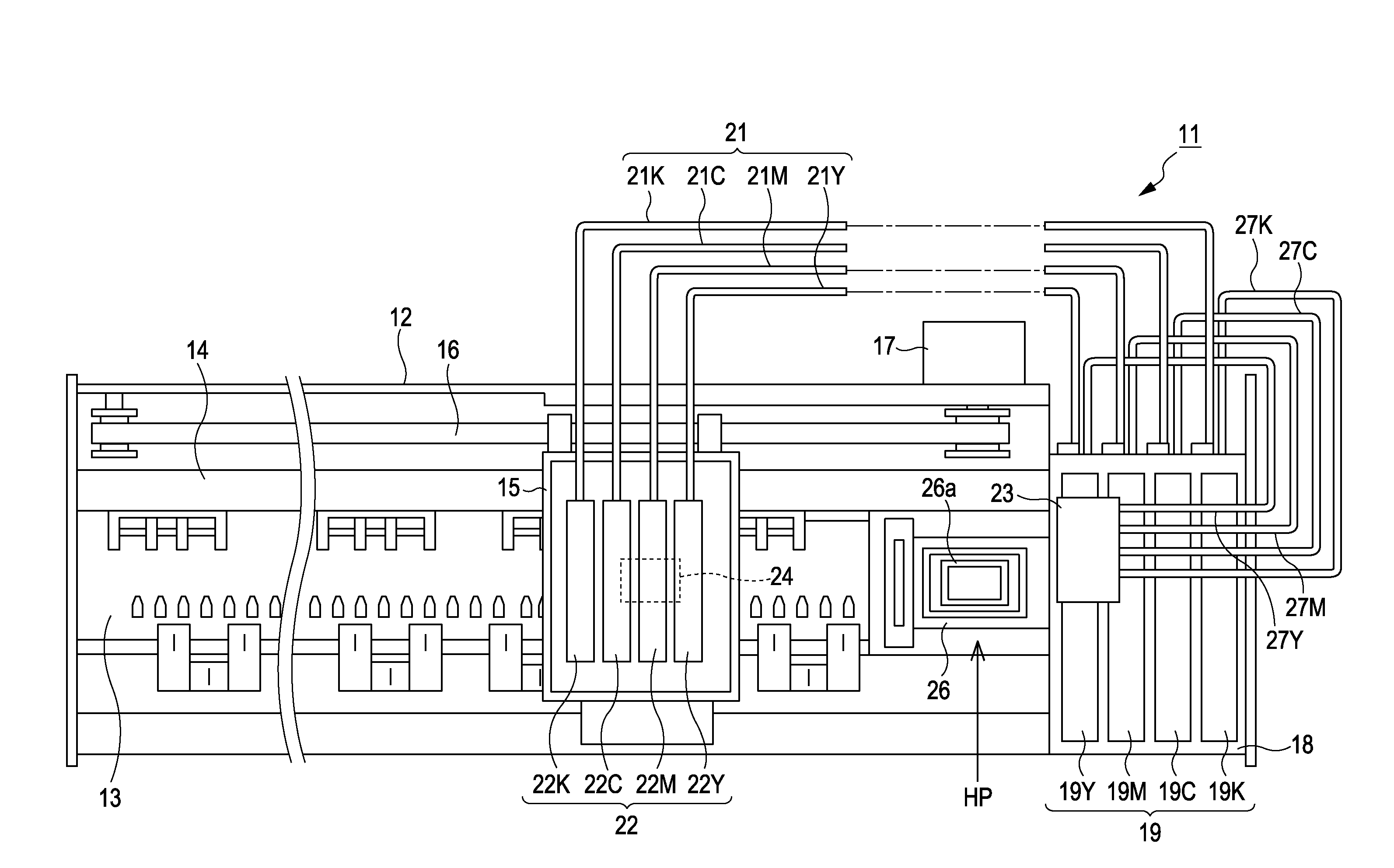
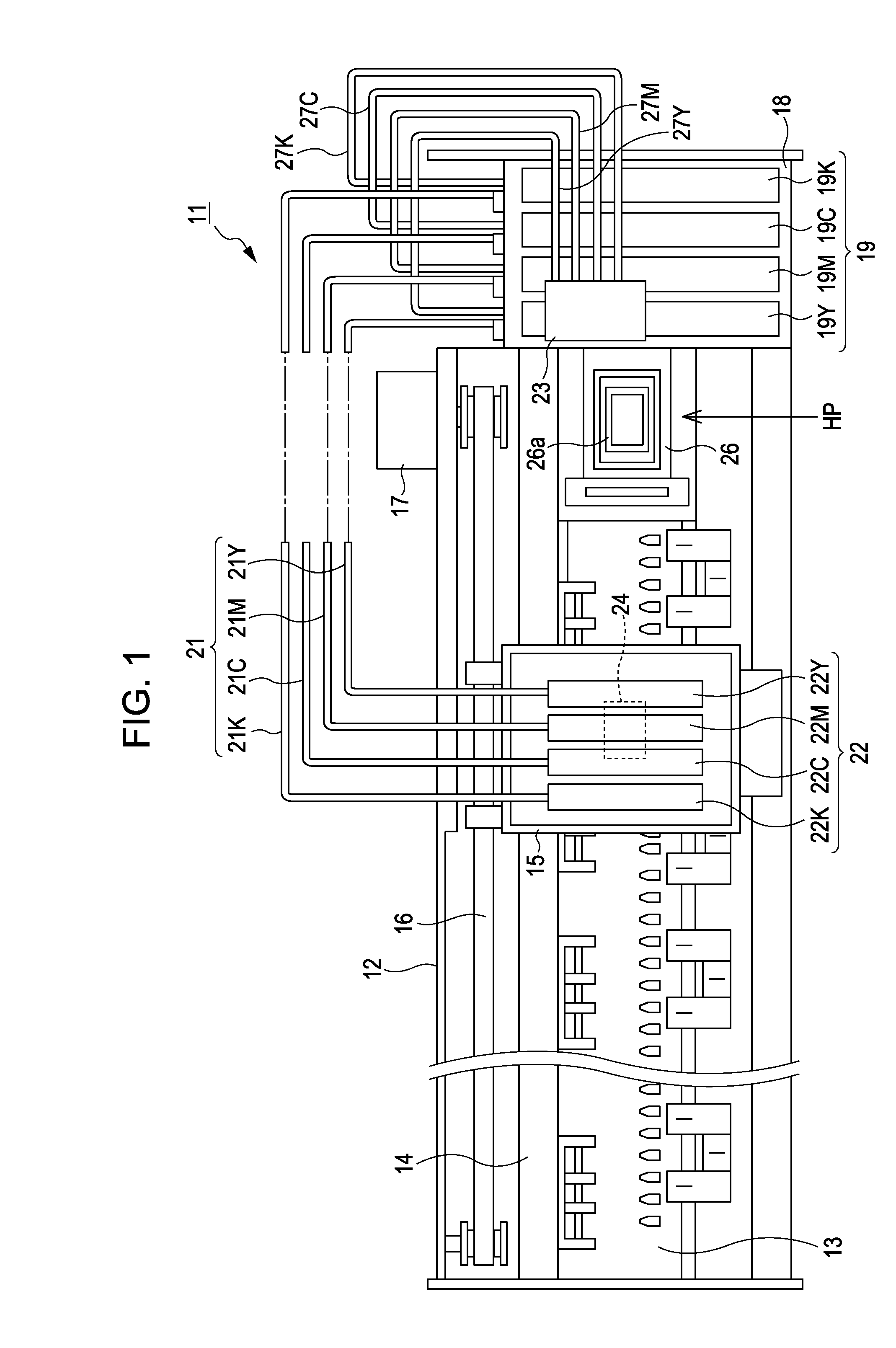
[0032]The first embodiment of the invention will be hereinafter described with reference to FIG. 1 to FIG. 3B.

[0033]As shown in FIG. 1, the ink jet printer 11 includes a substantially rectangular parallelepiped frame 12 with an open top, with a platen 13 being bridged at a lower part inside the frame 12 to extend along the lengthwise direction (left and right direction in FIG. 1) of the frame 12, which is the main scanning direction. The platen 13 is a support plate supporting a sheet of paper, which is one type of recording medium. Paper is fed on the platen 13 by a sheet feeding mechanism (not shown) in a sub scanning direction orthogonal to the main scanning direction.

[0034]Above and behind the platen 13 inside the frame 12 is bridged a bar-like guide member 14 to extend along the main scanning direction. This guide member 14 supports a carriage 15 to be movable along the axial direction of the guide member 14. This carriage 15 is connected to a carriage motor 17 through a timing...

second embodiment

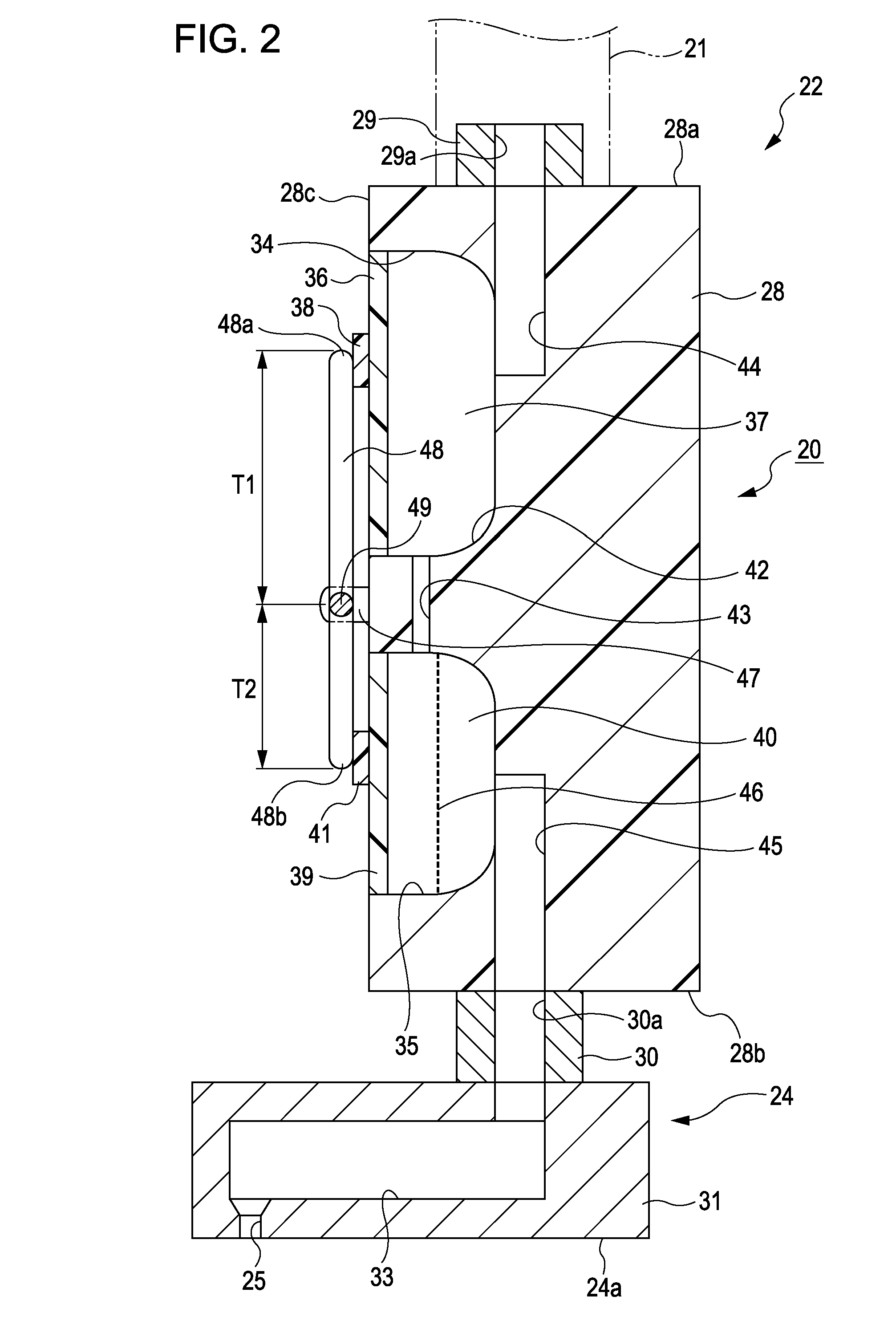
[0066]The second embodiment of the invention will be hereinafter described with reference to FIG. 4A and FIG. 4B. The second embodiment is different from the first embodiment in the following respects: The pressure chamber 37 and the filter chamber 40 are arranged side by side so that the first flexible thin film 36 and the second flexible thin film 39 are opposite each other. A bar-like transmission member is provided between the first flexible thin film 36 and the second flexible thin film 39. The same elements as those of the first embodiment are given the same reference numerals and will not be described in detail.

[0067]As shown in FIG. 4A, the bubble removing unit 22 includes an upstream side unit case 51 and a downstream side unit case 52. The upstream side, unit case 51 and the downstream side unit case 52 are formed separately and arranged side by side with a space therebetween in a horizontal direction. In the upstream side unit case 51, a connecting portion 29 is formed at...


PUM


Abstract

A liquid supply apparatus includes a liquid supply passage that supplies liquid from an upstream liquid supply source side to a downstream side where the liquid is consumed and a filter chamber midway in the liquid supply passage. The filter chamber has a filter that catches air bubbles in the liquid. The liquid supply passage has a pressure chamber upstream of the filter chamber. The pressure chamber is defined by a first movable wall that moves upon receiving pressure in the pressure chamber and by a second movable wall. The second movable wall receives force from the first movable wall upon displacement thereof. The second movable wall displaces toward the side of reducing the volume of the filter chamber by the force transmitted by the first movable wall when the pressure chamber and the filter chamber are pressurized from upstream side of the pressure chamber.

Description

[0001]This application claims the benefit of Japanese Patent Application No. 2009-051240, filed Mar. 4, 2009, which is expressly incorporated herein by reference in its entirety.BACKGROUND[0002]1. Technical Field[0003]The present invention relates to a liquid supply apparatus and a liquid ejecting apparatus.[0004]2. Related Art[0005]Generally, ink jet printers (hereinafter simply referred to as “printers”) are widely known as a liquid ejecting apparatus that ejects ink (liquid) from a nozzle of a recording head (liquid ejecting head) towards a target. In such printers, air bubbles present in the ink ejected from the recording head may cause a printing failure such as missing dots. Therefore, printers would normally include a filter in an ink supply passage upstream of a pressure chamber of the recording head, so that this filter traps foreign substance and air bubbles in the ink. Printers would perform maintenance in which, with a cap member being contacted on a nozzle forming surfa...

Claims


Application Information

Patent Timeline
IPC IPC(8): B41J2/175
CPCB41J2/17509B41J2/17596B41J2/17563
Inventor UEZAWA, HARUHISA
Owner SEIKO EPSON CORP
Why Eureka
Try Eureka