Television receiver

a receiver and receiver technology, applied in the field of television receivers, to achieve the effect of rational reduction of power consumption

Active Publication Date: 2010-09-09
MAXELL HLDG LTD
View PDF3 Cites 68 Cited by
  • Summary
  • Abstract
  • Description
  • Claims
  • Application Information

AI Technical Summary

Benefits of technology

The invention helps reduce power usage by shutting off the power source when multiple devices are being used simultaneously. This makes it easier to handle changes in the types of equipment that can connect to the network without causing problems or wasting energy.

Problems solved by technology

The technical problem addressed by this patent relates to how to efficiently use multiple devices within a television receiver system that all perform the same functions but require separate power supplies. This can lead to unnecessary power waste when certain devices are always on even though they may only be needed intermittently.

Method used


Image

  • Television receiver
  • Television receiver
  • Television receiver

Examples


Embodiment Construction

[0020]An embodiment of the present invention will be described referring to the drawings. In the embodiment, overlapping devices as tuners, that is, the tuner built in the television receiver and the tuner of the set top box connected as the external unit will be described for simplifying the explanation.

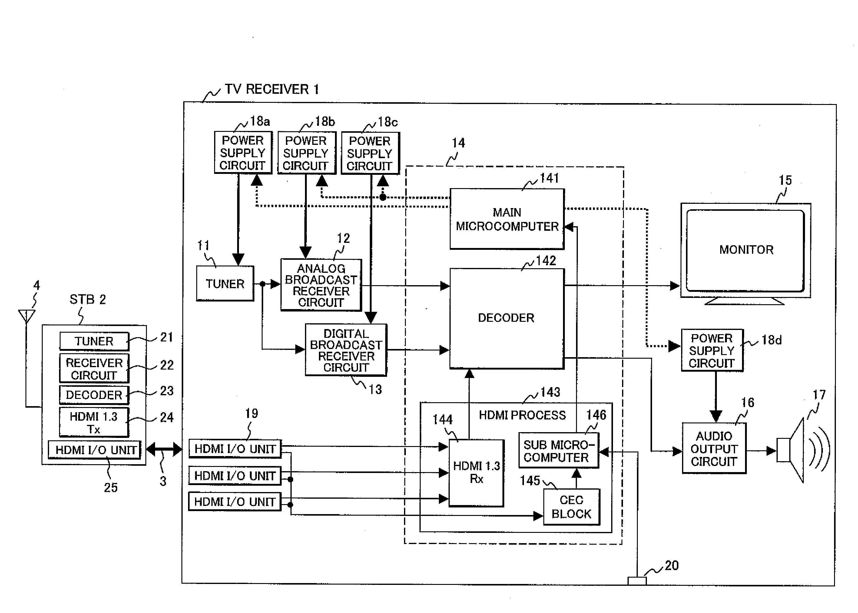
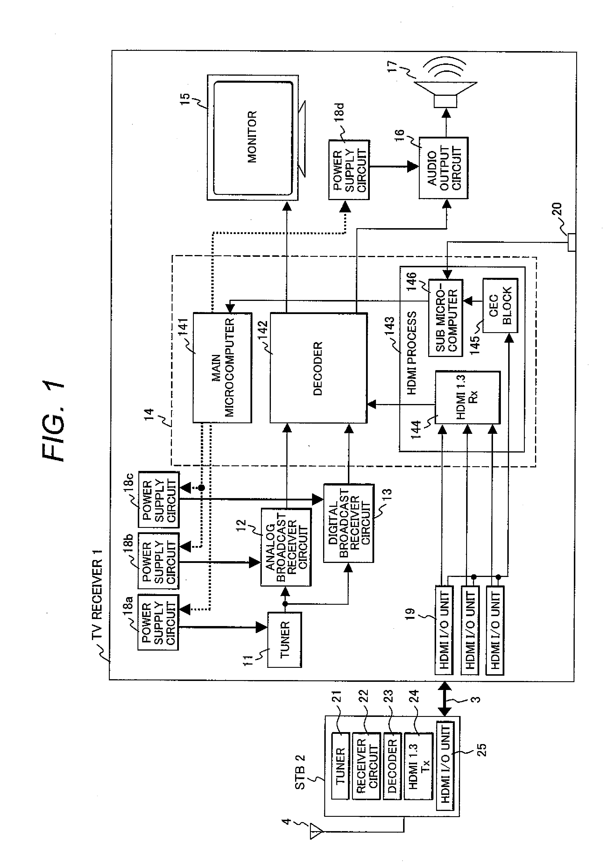
[0021]FIG. 1 is a block diagram showing a structure of a television receiver 1 according to an embodiment of the present invention.

[0022]The television receiver 1 includes a tuner 11, an analog broadcast receiver circuit 12, a digital broadcast receiver circuit 13, a signal processing circuit block 14, a monitor 15, an audio output circuit 16, a speaker 17, power supply circuits 18a to 18d, an HDMI I / O unit 19, and a remote control light receiving unit 20. The signal processing circuit block 14 includes a main microcomputer (control section) 141, a decoder 142, and an HDMI process unit 143.

[0023]The tuner 11 receives a television broadcast signal corresponding to a required channel ...


PUM


Abstract

A television receiver cuts power supply to its built-in device which is overlapped with that of the external unit connected to the television receiver for reducing power consumption to cope with diversification of the external unit. The television receiver includes the tuner which receives a television broadcast signal, an external unit connection portion which connects the external unit with the HDMI cable, the HDMI process unit which acquires unit information data from the connected external unit to transmit video/audio data, and the power supply circuit which supplies power to the tuner. If the HDMI process unit determines that the connected external unit includes the same function as the tuner, the control unit allows the power supply circuit to stop power supply to the tuner.

Description


Claims


Application Information

Patent Timeline
Owner MAXELL HLDG LTD
Why Eureka
Try Eureka