Unlock instant, AI-driven research and patent intelligence for your innovation.

Control device, magnetic disk device, and iw sensitivity calculating method

a technology of sensitivity calculation and control device, which is applied in the direction of data recording, magnetic recording, instruments, etc., can solve the problems of large amount of time and cos

Inactive Publication Date: 2010-09-09
TOSHIBA STORAGE DEVICE CORP
View PDF0 Cites 4 Cited by
  • Summary
  • Abstract
  • Description
  • Claims
  • Application Information

AI Technical Summary

Problems solved by technology

If the Iw sensitivity is measured by a measuring instrument for each head, a large amount of time and cost are required.

Method used


Image

  • Control device, magnetic disk device, and iw sensitivity calculating method
  • Control device, magnetic disk device, and iw sensitivity calculating method
  • Control device, magnetic disk device, and iw sensitivity calculating method

Examples


first embodiment

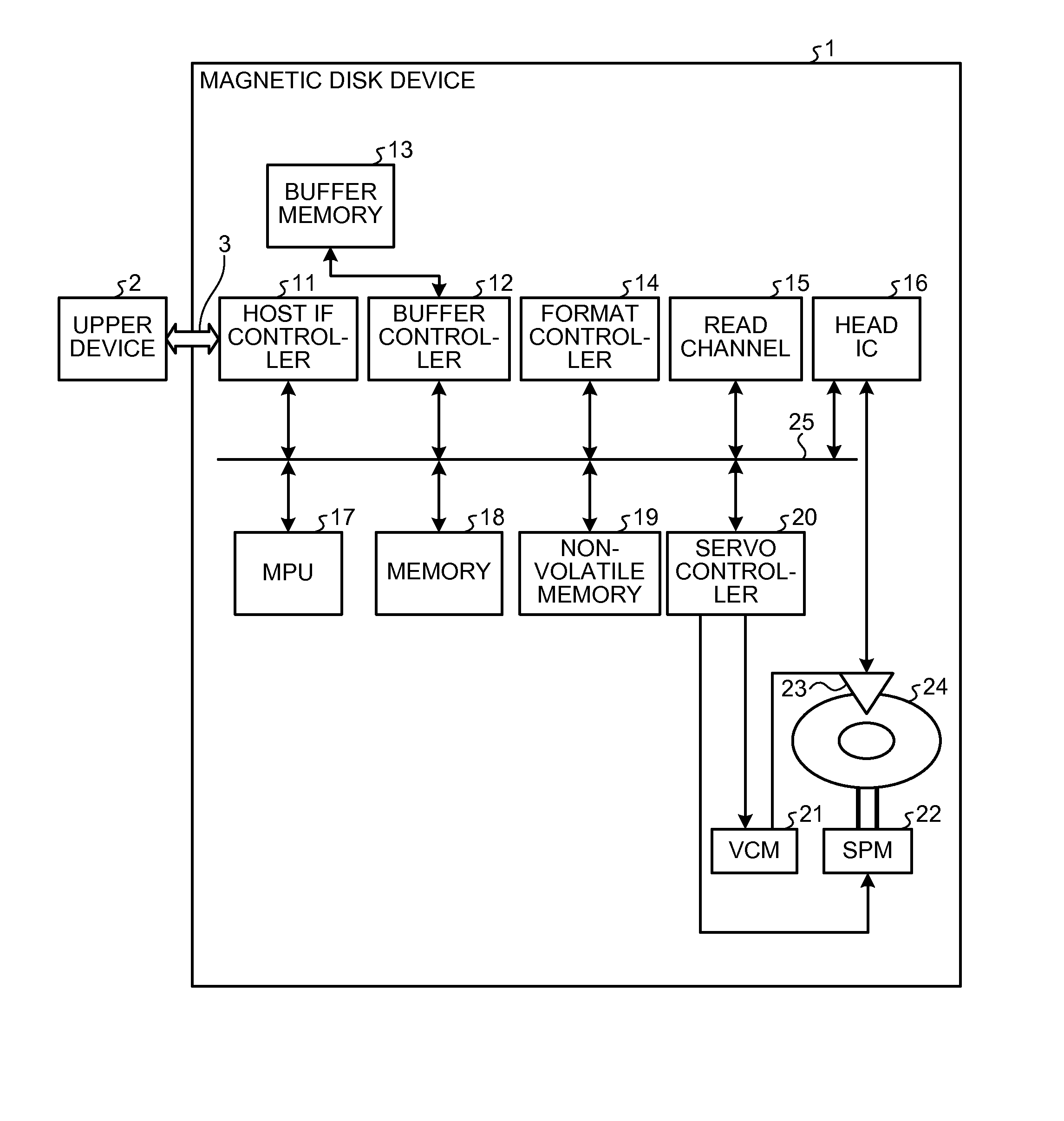
[0041]As illustrated in FIG. 4, the magnetic disk device 1 of the first embodiment comprises a writer 901, a reader 902, a setting module 903, an acquiring module 904, and a calculator 905 as functions. The writer 901 writes a signal in the disk medium 24 by the read / write head 23. The reader 902 reads a signal from the disk medium 24 by the read / write head 23. The setting module 903 sets a write current (electric parameter) of the read / write head 23. The acquiring module 904 acquires a VGA gain value, an AGC input signal amplitude value, and a VGA output signal amplitude value. The acquiring module 904 instructs the writer 901 to write a signal, the reader 902 to read a signal, and the setting module 903 to set a write current. The calculator 905 calculates Iw sensitivity, based on the value acquired by an acquiring module 906, and acquires the Iw sensitivity. The individual modules are functions that are substantially realized by the MPU 17.

[0042]Next, the operation of the magneti...

second embodiment

[0051]First, to calculate the amplitude ratio of the read signals based on the HSC output, information (hereinafter, “correlation information”) indicating a correlation between the HSC output and the read signal amplitude illustrated in FIG. 10 is stored in the memory 18 of the magnetic disk device 1. The correlation information may be stored in a system area of the disk medium 24. In the second embodiment, the correlation information is an approximated curve (primary expression) based on HSC output values measured several times in advance and amplitude values of the read signals corresponding to the HSC output values. When the read signal amplitude value is defined as y, the HSC output value is defined as x, and constants are defined as a and b, the approximated curve is represented by an expression of y=ax+b. The constants a and b are calculated by a least-square method. Specifically, the constants a and b are calculated by expressions illustrated in FIG. 11. In these expressions,...

third embodiment

[0058]In the third embodiment, the write operation of the dummy signal by the writer 901 and the read operation of the observed pattern by the reader 902 are performed with an arbitrary servo frame. In FIG. 13, the read operation of the observed pattern is performed once for every 5 servo frames. That is, after the dummy signal is written by the four servo frames, the read operation of the observed pattern corresponding to one servo frame is performed. The reader 902 reads the observed pattern of the servo frame unit several times.

[0059]With respect to the read operation of the observed patterns, the acquiring module 904 acquires the read value (the VGA gain or the value of the read signal amplitude based on the HSC output) several times. The acquiring module 904 sets the sum or the average of the read values acquired several times as the read value. In the case of the addition, instead of the specific write current (or heater power), a range of the write current is set to each cond...


PUM


Abstract

According to one embodiment, a control device includes a writer, a setting module, a reader, and an Iw sensitivity acquiring module. The writer writes a signal by the magnetic head. The setting module sets an electric parameter to the magnetic head. The reader reads the signal by the magnetic head. The Iw sensitivity acquiring module acquires Iw sensitivity of the magnetic head. The Iw sensitivity acquiring module includes a first acquiring module, a second acquiring module, and an Iw sensitivity calculator. The first acquiring module acquires a predetermined output value related to control of a signal having a predetermined frequency. The second acquiring module acquires a predetermined output value related to control of the signal having the predetermined frequency. The Iw sensitivity calculator calculates the Iw sensitivity of the magnetic head based on the predetermined output values acquired by the first and second acquiring modules.

Description

CROSS-REFERENCE TO RELATED APPLICATIONS[0001]This application is based upon and claims the benefit of priority from Japanese Patent Application No. 2009-52975, filed Mar. 6, 2009, the entire contents of which are incorporated herein by reference.BACKGROUND[0002]1. Field[0003]One embodiment of the invention relates to a control device, a magnetic disk device, and an Iw sensitivity calculating method.[0004]2. Description of the Related Art[0005]To ensure the reliability of a magnetic disk device, technology for controlling the head flying height has been known. As one example of such technology, dynamic fly height (DFH) has been known. The DFH is a technology for protruding a head element at a front end of a head by heat emitted from a heater incorporated in the head. The DFH will be specifically described using FIG. 16. FIG. 16 illustrates an example of the DFH.[0006]As illustrated in FIG. 16, the DFH thermally expands an insulating film having a head element (a write core and a read...

Claims


Application Information

Patent Timeline
IPC IPC(8): G11B5/02G11B27/36
CPCG11B5/3136G11B5/40G11B2005/0013G11B5/6005G11B5/6064G11B5/455
Inventor SATO, HIROAKI
Owner TOSHIBA STORAGE DEVICE CORP