Lighting equipment

Inactive Publication Date: 2010-09-09
TOSHIBA LIGHTING & TECH CORP +1
View PDF32 Cites 11 Cited by
  • Summary
  • Abstract
  • Description
  • Claims
  • Application Information

AI Technical Summary

Benefits of technology

[0009]According to the lighting equipment, since the second reflector is disposed outside the direct light emission area where direct light from the semiconductor light-emitting element is emitted from the emission opening of the first reflector, it is possible to pick up the direct light from the semiconductor light-emitting element, which is blocked by the second reflector, and the light pick-up efficiency can be improved.
[0015]According to the present invention, since the rise surface is formed at the inner edge of the passage hole of the first reflector, a width dimension necessary to mold the first reflector can be secured, and light reflected by the rise surface can be emitted from the emission opening without being re-reflected by the reflection surface of the first reflector by causing the rise surface to be tilted so as to be widened toward the emission opening, wherein the light pick-up efficiency can be improved.

Problems solved by technology

However, where the baffle is used to prevent glare, if the edge part of the upper side opening of the baffle is located near the emission opening of the reflector, a part of the light emitted from the emission opening of the reflector is blocked by the edge part of the upper side opening of the baffle, causing a problem in which the light pick-up efficiency of picking up outer light of the LED is lowered.
In particular, since the direct light from the LED is blocked by the baffle, this easily adversely lowers the light pick-up efficiency.

Method used


Image

  • Lighting equipment
  • Lighting equipment
  • Lighting equipment

Examples


Embodiment Construction

[0023]Hereinafter, a description is given of one embodiment of the present invention with reference to the drawings.

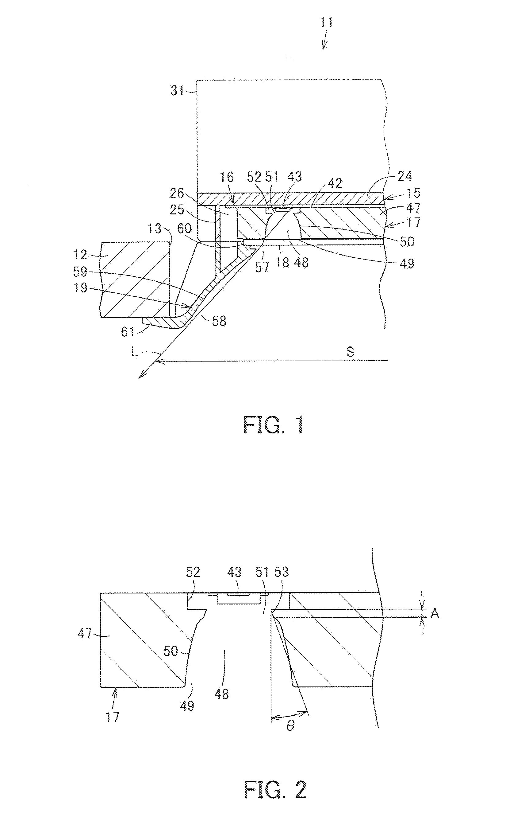
[0024]As shown in FIG. 1, lighting equipment 11 is, for example, a downlight which is embedded and installed in a circular embedding hole 13 provided in a ceiling member 12 such as a ceiling plate.

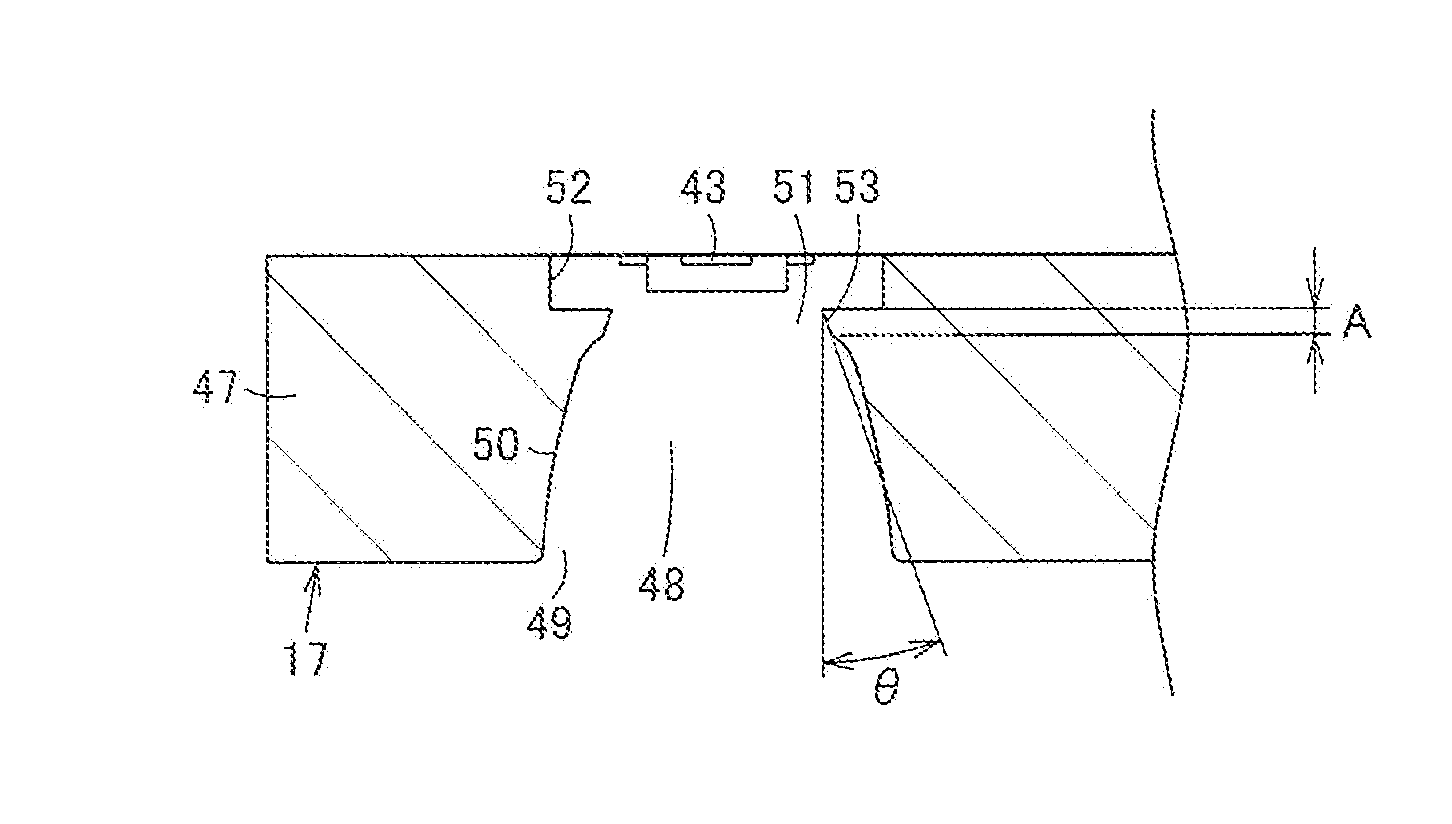
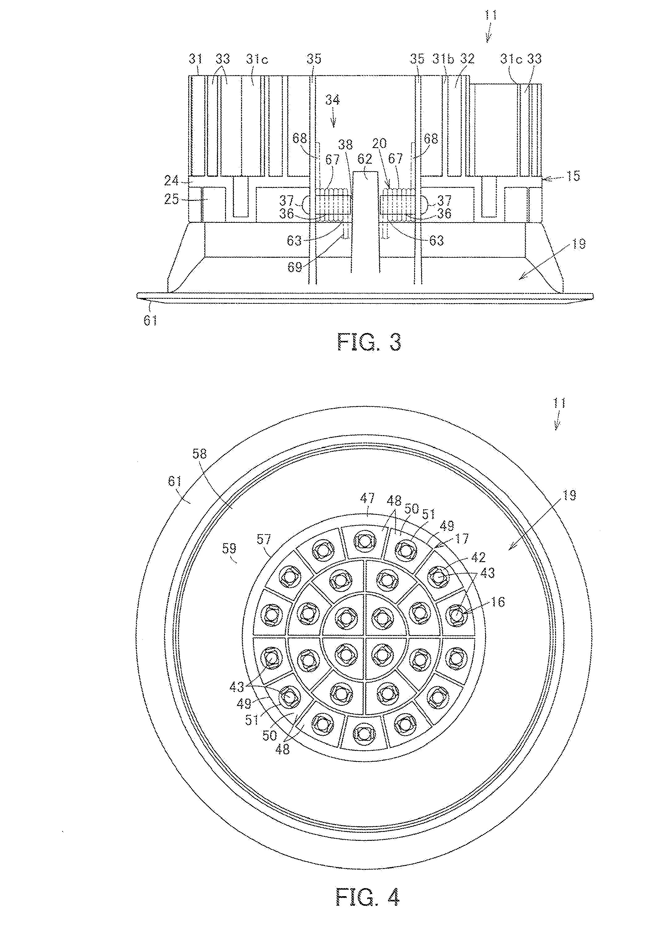
[0025]As shown in FIGS. 1 to 6, the lighting equipment 11 is provided with an equipment main body 15, a light source module 16 attached to the underside of the equipment main body 15, a reflector 17 acting as the first reflector, which is attached to the underside of the light source module 16, a transparent cover 18 disposed on the underside of the reflector 17, a baffle 19 acting as the second reflector, which is attached to the underside of the equipment main body 15, a pair of attaching springs 20 which acts to attach the equipment main body 15 to the ceiling member 12 and is attached to the outer side surface of the equipment main body 15, and a power source unit and a t...


PUM


Abstract

LEDs, a reflector, and a baffle are disposed on the underside of the equipment main body. An emission opening for emitting light of the LEDs and a reflection surface for emitting light of the LEDs from the emission opening by reflecting the same are provided in the reflector. The baffle is disposed outside the direct light emission area where direct light from the LEDs is emitted from the emission opening of the reflector. The direct light from the LEDs can be picked up without being blocked by the baffle, and the light pick-up efficiency can be improved.

Description

INCORPORATION BY REFERENCE[0001]The present invention claims priority under 35 U.S.C. §119 to Japanese Patent Application No. 2009-052118 filed on Mar. 5, 2009. The contents of these applications are incorporated herein by reference in their entirety.FIELD OF THE INVENTION[0002]The present invention relates to lighting equipment using a semiconductor light-emitting element as a light source.BACKGROUND OF THE INVENTION[0003]Conventionally, as described in Japanese Laid-Open Patent Publication No. 2008-204692, there is lighting equipment such as a downlight using an LED as a semiconductor light-emitting element. The lighting equipment has a substrate disposed at the equipment main body, which is mounted with a plurality of LEDs, has a reflector disposed at the underside of the substrate, which controls the distribution of light from the LEDs, has a transparent cover disposed at the underside of the reflector, and further has a decorative frame disposed at the lower part of the equipme...

Claims


Application Information

Patent Timeline
IPC IPC(8): F21V7/00
CPCF21S8/02F21V7/0025F21V7/0083F21V7/09F21V21/04F21V29/77F21V21/046F21V29/507F21V29/75F21V29/76F21Y2101/02F21Y2115/10
Inventor HIGUCHI, KAZUNARIMORIYAMA, TAKAYOSHIHASHIMOTO, SUMIOWATANABE, SATOSHIKURAMOCHI, HIROYUKI
Owner TOSHIBA LIGHTING & TECH CORP
Why Eureka
Try Eureka