Wireless communication method for wireless LAN system, wireless communication device and wireless terminal

a wireless lan and wireless terminal technology, applied in sustainable communication technology, high-level techniques, climate sustainability, etc., can solve problems such as communication delay, inability to receive packets, and increase the possibility of packet reception delay, so as to save power and suppress reception delay

Active Publication Date: 2010-09-09
NEC PLATFORMS LTD
View PDF4 Cites 34 Cited by
  • Summary
  • Abstract
  • Description
  • Claims
  • Application Information

AI Technical Summary

Benefits of technology

[0015]Thus, according to the present invention, it is possible to suppress reception delay from a parent device, while

Problems solved by technology

However, on the other hand, the possibility of occurrence of a packet reception delay rises.
However, the STA is in a doze state

Method used


Image

  • Wireless communication method for wireless LAN system, wireless communication device and wireless terminal
  • Wireless communication method for wireless LAN system, wireless communication device and wireless terminal
  • Wireless communication method for wireless LAN system, wireless communication device and wireless terminal

Examples


first exemplary embodiment

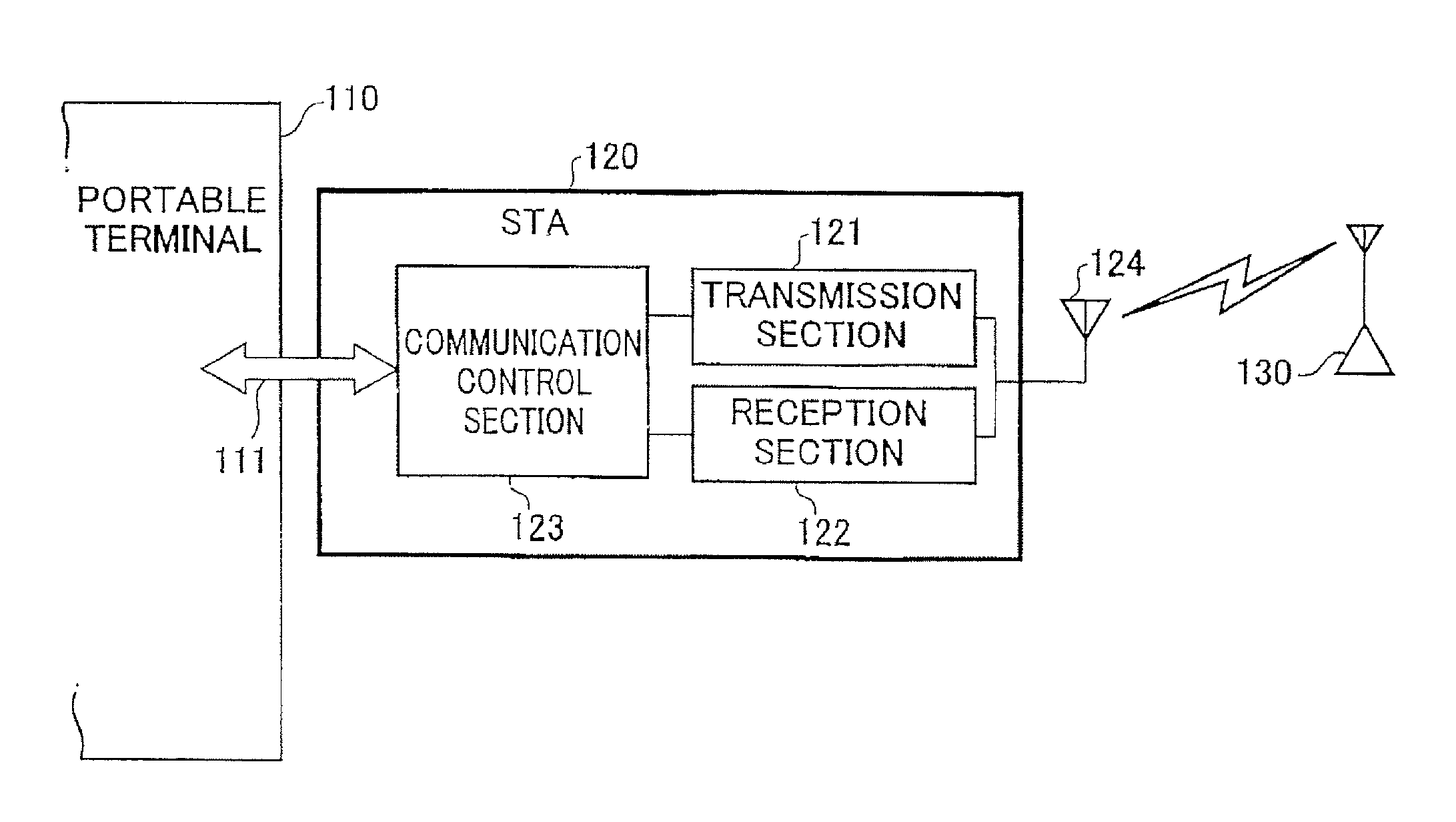
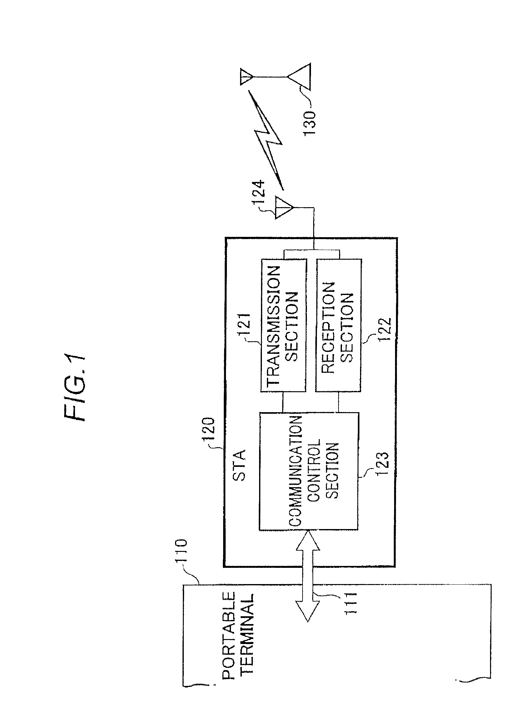
[0026]FIG. 1 shows the configuration of a first exemplary embodiment of the present invention. Wireless LAN card (to be referred to as “STA” hereinafter) 120 that corresponds to a wireless communication device according to the present invention is a device adapted to a power management mode of wireless LAN as defined in the above-described NPL 1 and connected to a portable terminal 110 through a communication bus 111. AP 130 is a parent device that transmits a beacon signal at constant intervals.

[0027]As shown in FIG. 1, the STA 120 includes a transmission section 121, a reception section 122, a communication control section 123 and an antenna 124. The transmission section 121 transmits wireless signals to the AP 130 by way of the antenna 124. The reception section 122 receives wireless signals from the AP 130 by way of the antenna 124. The communication control section 123 controls the wireless communication with the AP 130 by a control signal supplied from the portable terminal 11...

second exemplary embodiment

[0057]FIG. 8 shows the configuration of a wireless LAN system 1000 according to second exemplary embodiment of the present invention. The wireless LAN system 1000 includes a wireless terminal 210, access points 220 and a server 230, the access points 220 and the server 230 being connected to a wired LAN 240. In the wireless LAN system 1000, the wireless terminal 210 accesses the server 230 by way of one of the access points 220 by means of wireless LAN communication.

[0058]The wireless terminal 210 has a wireless LAN module 211 that can operates in a power management mode described in the above NPL 1. The communication section 212 of the wireless LAN module 211 is in charge of wireless communications in a power management mode with regard to the access points 220. The control section 213 is in charge of controlling the listen interval of beacon signal and controlling switching of the state (doze or awake) of the wireless terminal 210.

[0059]The process of controlling the beacon listen...


PUM


Abstract

In a wireless communication method of a wireless communication device to which a power management mode of a wireless LAN is applied and to which a parent device communicates, the method includes updating a listen interval of receiving a beacon signal from a parent device to be shorter than a current listen interval in response to a data transmission to the parent device; and periodically increasing the updated listen interval between the time span from the data transmission to a next data transmission, wherein reception of the beacon signal is carried out after switching from a doze state to an awake state.

Description

CROSS REFERENCE TO RELATED APPLICATIONS[0001]The present application claims the benefit of Japanese Patent Application No. 2009-053506, filed Mar. 6, 2009 and Japanese Patent Application No. 2009-071843, filed Mar. 24, 2009, which are hereby incorporated by reference in its entirety.TECHNICAL FIELD[0002]The present invention relates to a wireless communication method in a power management mode of a wireless LAN and a wireless communication device and a wireless terminal having a power management mode function.BACKGROUND ART[0003]Power management modes such as the one described in NPL 1, which will be described hereinafter, are known as techniques for suppressing the power consumption of a battery-driven wireless terminal for a wireless LAN. In a power management mode, such a wireless terminal maintains a doze state of operating at low power during waiting for communication and switches to an awake state from the doze state when communication becomes necessary. More specifically, in ...

Claims


Application Information

Patent Timeline
IPC IPC(8): H04W52/02H04W88/12
CPCH04W52/0229Y02D30/70
Inventor SUMIDA, HARUHIKOKAWAHARA, TERUO
Owner NEC PLATFORMS LTD
Why Eureka
Try Eureka