Sharpening device for knife blades

a technology of sharpening device and knife blade, which is applied in the direction of grinding machine, application, other manufacturing equipment/tools, etc., can solve the problems of increased inability to guide knives with perfect stability in the guiding slot, and inability to ensure the accuracy of sharpening, so as to prevent unnecessary wear of knife blades, improve the sharpening effect, and minimize irregular movements

Active Publication Date: 2010-09-09
FRIEDR DICK
View PDF8 Cites 2 Cited by
  • Summary
  • Abstract
  • Description
  • Claims
  • Application Information

AI Technical Summary

Benefits of technology

[0009]Since knife blades are usually produced from magnetic steel, i.e. steel that is attracted by a magnet, a knife blade that is inserted into the guiding slot to be sharpened is attracted by the magnet in the direction of the knife abutment surface and retained there by means of magnetic force. For this reason, the knife blade is always guided on the knife abutment surface in a defined fashion during sharpening. Irregularities in the guidance of the movements during sharpening are minimized, thereby improving the sharpening result. The person guiding the knife, the blade of which is sharpened, during the sharpening process, feels the attraction between the magnet and the knife blade and a frictional force that is generated between the knife abutment surface and the knife blade. The person thereby gets the same impression as during sharpening of a blade on a sharpening steel. There are also magnetic sharpening steels. The person will therefore tend to reduce the number of times that he / she guides the knife blade through the guiding slot to the required degree to prevent unnecessary wear of the knife blade. The sharpening effect is improved. The magnets retain the generated sharpening dust and the sharpening rods on the sharpening device to prevent them from contaminating the food.
[0010]At least one magnet is advantageously mounted to the base plate in the area of each of the two walls of the base plate, which are opposite to each other and form the guiding slot. The magnet(s) mounted in the area of one wall is / are thereby arranged to have a pole orientation repelling the magnet(s) mounted in the area of the other wall. During insertion into the guiding slot, the knife blade is further moved in the direction of one of the walls, since only an unstable state of equilibrium would be possible between the repelling fields. The knife blade, however, is additionally repelled by the magnets that are mounted to the respective opposite wall due to the field induced in the knife blade. This all results in that an increased force acts on the knife blade in the direction of one of the walls. For this reason, the positive effect achieved by the invention can be obtained by smaller, i.e. weaker magnets.
[0013]When the field strength of the magnets thereby increases from an insertion opening to an area of an end of the guiding slot facing away from the insertion opening, the person guiding the knife can feel when the knife blade has reached the end of the guiding slot facing away from the insertion opening while he / she is guiding the knife blade through the guiding slot. The person will then stop pushing the knife blade further down into the guiding slot, thereby preventing the knife blade from damaging the end of the guiding slot facing away from the insertion opening. The service life of the inventive sharpening device is thereby increased compared to conventional sharpening devices of this type.
[0014]In a particularly advantageous variant, pre-positioning means are provided on the base plate, which are designed to fix at least one of the magnets. These pre-positioning means may be designed as simple locking openings for the magnet(s). However, it is also possible to provide a device, which is preferably lockable, for moving a magnet along the guiding slot. In this fashion, any user can position the magnets in a flexible fashion to obtain his / her personal optimum sharpening effect. The magnets may e.g. be positioned in different ways by left-handed and right-handed persons, respectively.

Problems solved by technology

For this reason, the knife blade is not guided with perfect stability in the guiding slot.
This can impair the sharpening result.
The person guiding the knife during sharpening may therefore get the impression (sharpening impression) that the sharpening effect is only small such that the knife blade is guided through the sharpening device an excessive number of times, which is unnecessary and causes increased wear of the knife blade.

Method used


Image

  • Sharpening device for knife blades
  • Sharpening device for knife blades
  • Sharpening device for knife blades

Examples


Embodiment Construction

[0019]The figures of the drawing show the subject matter of the invention in a highly schematized fashion and are not to be taken to scale. The individual components of the inventive subject matter are illustrated in such a fashion that their construction is clearly visible.

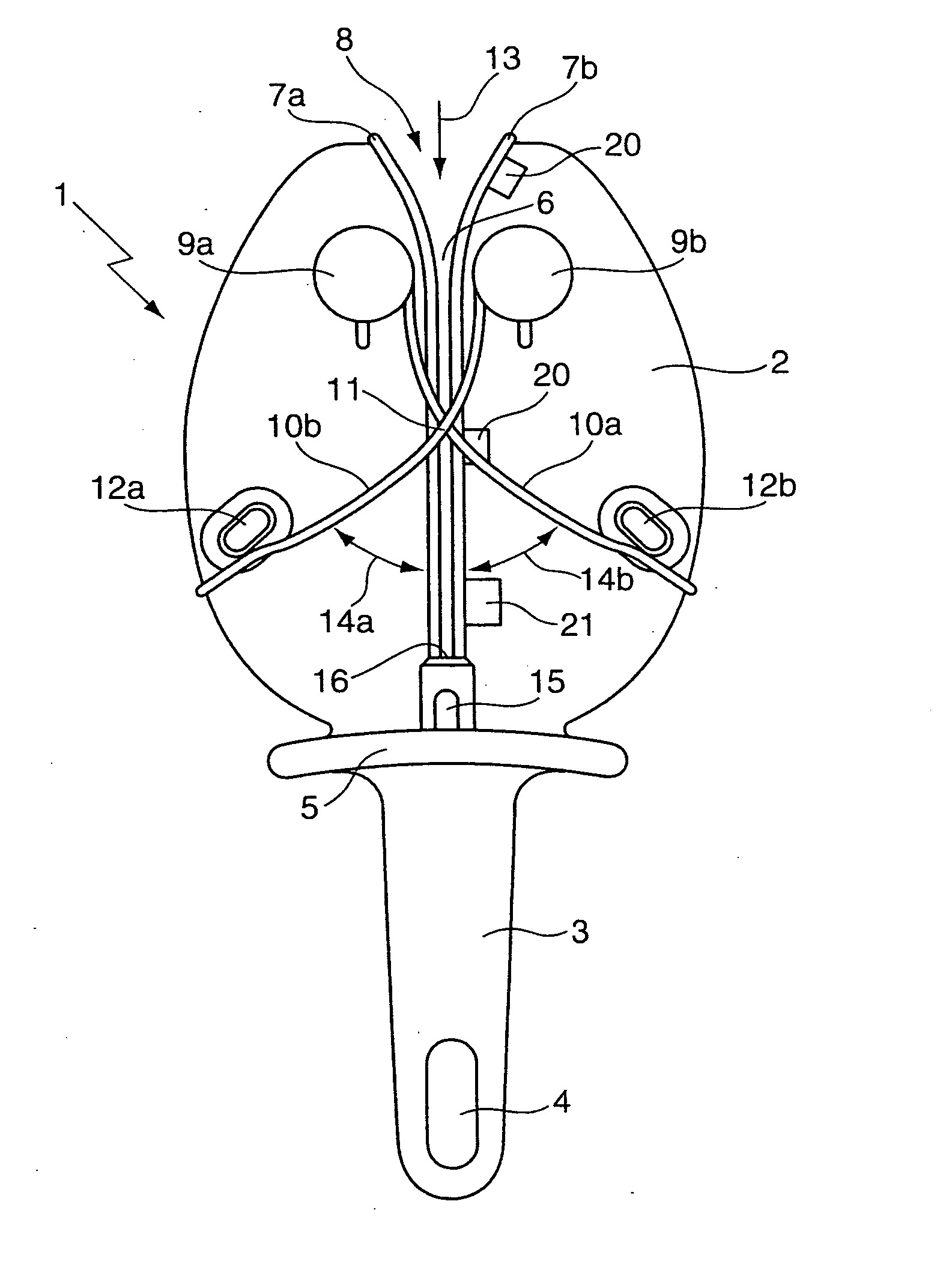
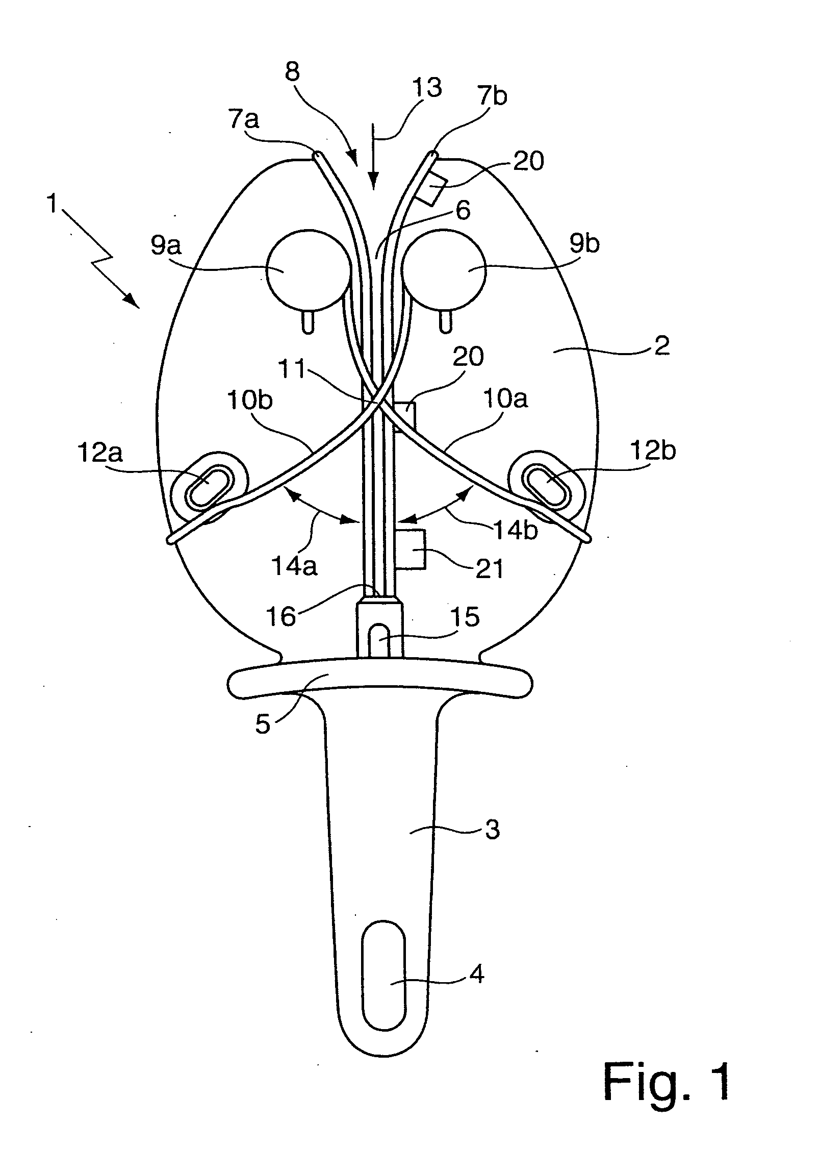
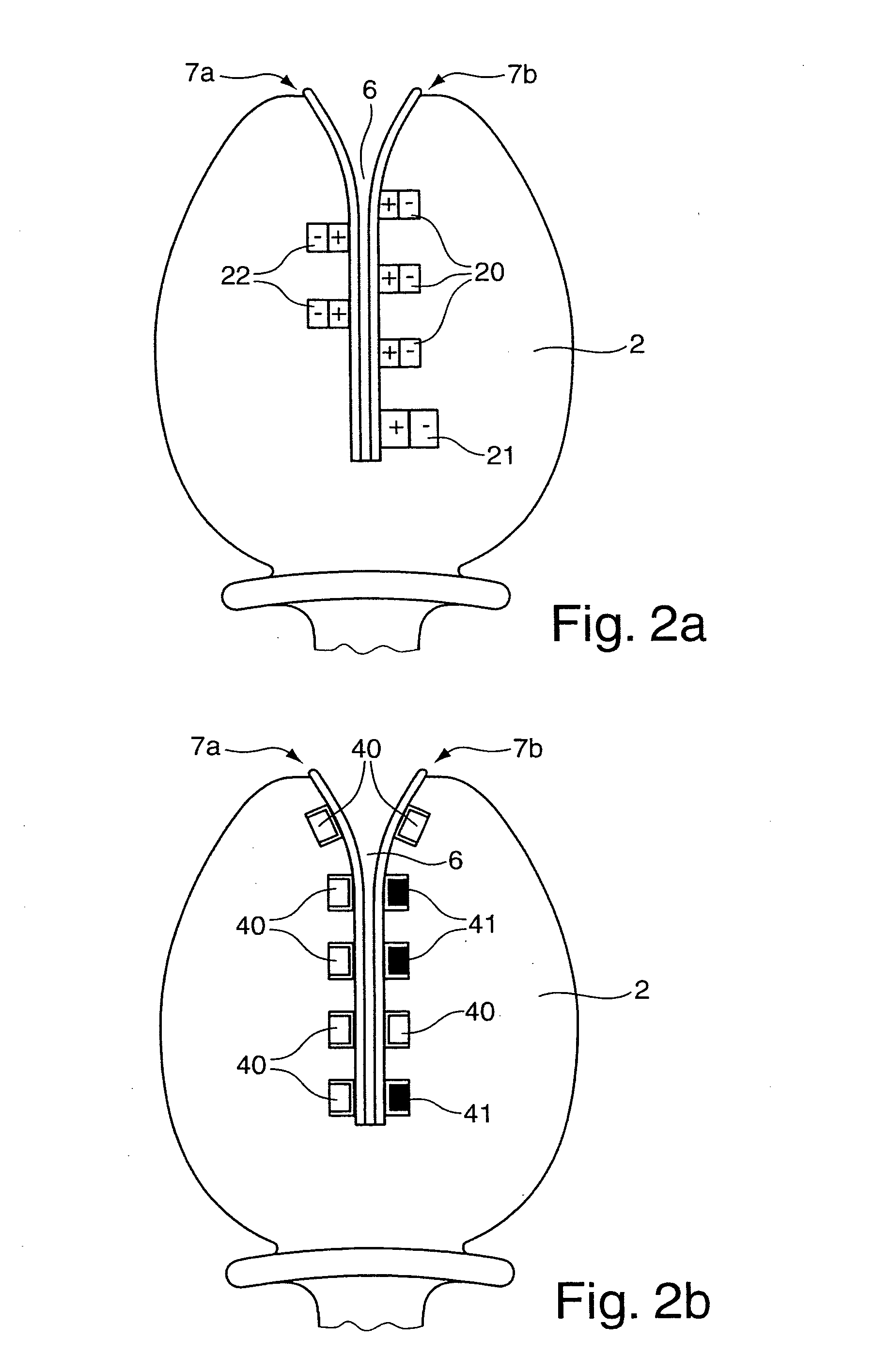
[0020]FIG. 1 shows an inventive sharpening device 1 with a substantially oval base plate 2 and a handle 3 that is formed as a handhold and has a recess 4. The dimensions and the material, in the present case plastic material, of the sharpening device 1 are selected in such a fashion that the sharpening device 1 can be held by a user in one hand. A protecting plate 5 is provided between the base plate 2 and the handle 3 for protecting the hand holding the sharpening device 1. A gap-like guiding slot 6 is cut into the base plate 2 and extends over almost its entire length. The guiding slot is formed by two walls of the base plate 2 disposed opposite to each other. Each wall forms a knife abutment surface 7a and 7b....


PUM

PropertyMeasurementUnit
elastically resilient restoring forceaaaaaaaaaa
areaaaaaaaaaaa
field strengthaaaaaaaaaa

Abstract

A sharpening device 1 for knife blades comprising a base plate 2 with a guiding slot 6, designed as an incision in the base plate 2, for a knife blade to be sharpened and sharpening rods 10a, 10b disposed on both sides of the guiding slot 6 to be pivotable against an elastically resilient restoring force, wherein the guiding rods 10a, 10b intersect at a point of intersection 11 in the area of the guiding slot 6. At least one of the two walls of the base plate 2, which are disposed opposite to each other and form the guiding slot 6, thereby forms a knife abutment surface 7a, 7b and at least one magnet 20, 21, 22 is mounted to the base plate 2 in the area of the knife abutment surface 7a, 7b.

Description

[0001]This application claims Paris Convention priority of DE 10 2009 011 827.6 filed Mar. 4, 2009 the complete disclosure of which is hereby incorporated by reference.BACKGROUND OF THE INVENTION[0002]The invention concerns a sharpening device for knife blades, comprising a base plate with a guiding slot formed as an incision in the base plate for a knife blade to be sharpened, and sharpening rods that are disposed on both sides of the guiding slot such that they can be pivoted against an elastically resilient restoring force, wherein the sharpening rods intersect at a point of intersection in the area of the guiding slot.[0003]A sharpening device of this type, which is disclosed e.g. in U.S. Pat. No. 6,866,569 B2 or DE 10 2006 041 538 B3, is used to sharpen and reshape knife blades that have become blunt through use. In order to prevent damage to the base plate, which is usually produced from plastic material, and to prevent soiling of the knife blade as well as of the material cut...

Claims


Application Information

Patent Timeline
Patent Type & Authority Applications(United States)
IPC IPC(8): B24D15/08B24B3/36
CPCB24B3/54
Inventor LOEHNERT, HORST
Owner FRIEDR DICK
Why Eureka
Try Eureka