Turbo-Pneumatic Assist for Electric Motor Starting

a technology of electric motor and assist device, which is applied in the direction of engine starter details, engine control, engine start-up, etc., can solve the problems of increasing the difficulty of employing proximate to communities or where facilities may be (more logically) needed, the use of fossil fuel based prime movers is becoming less and less attractive, and the effect of reducing the effect of electric motor acting, reducing the effect of inrush current and energy consumption

Inactive Publication Date: 2008-12-04
SMITHS AEROSPACE INC
View PDF8 Cites 3 Cited by
  • Summary
  • Abstract
  • Description
  • Claims
  • Application Information

AI Technical Summary

Benefits of technology

[0013]The present invention provides a new and improved prime mover system and method that overcomes one or more of the above described and other problems existing in the art. Particularly, the present invention provides a new electric motor prime mover that has reduced inrush currents when starting the electric motor. The invention provides a pneumatic starting assist system that assists startup of the electric motor to reduce the effects of the electric motor acting like a short-circuit upon activation. The pneumatic starting assist system operates on compressed gas rather than electricity. This reduces the large inrush currents and energy consumption typically associated with starting electric motors using electricity.
[0015]The coupling may include gears, belts, chains / sprockets or a CVT. A clutch interposed within the drive system, between the pneumatic motor and the armature of the electric motor may allow the rotating components of the pneumatic motor to be selectively, rotationally isolated from the armature. Further, the clutch may be configured to allow the armature to overrun the rotational components of the pneumatic motor without allowing the armature to accelerate or drive the components of the pneumatic motor to prevent unnecessary wear on the components of the pneumatic motor.
[0017]In one form, the new and improved method of starting an electric motor assists startup of the electric motor by initially rotating the armature of the electric motor without the use of electricity. This method reduces the peak initial electrical energy consumption and inrush currents experienced during startup of the electric motor prime movers. More particularly, the method includes activating a pneumatic motor and mechanically driving the armature of an electric motor with the pneumatic motor. After the armature is rotating via mechanical means, the armature is driven, at least in part, electrically. In a preferred method, the method includes activating the pneumatic motor and then operably coupling the pneumatic motor to the armature, such as by engaging a clutch. In another method, mechanically driving the armature originally occurs when no electricity is driving the armature. In a further method, after the electric motor is electrically driven, the pneumatic motor is deactivated, such as by means of a clutch or by preventing air flow through the pneumatic motor to prevent unnecessary wear and tear on the pneumatic motor.

Problems solved by technology

Reciprocating combustion engines and combustion gas turbine engines use fossil fuels and generate harmful exhaust emissions and many other by-products of combustion.
With stricter government regulations on emissions and pollutants, ever increasing and volatile fissile fuel costs, the use of fossil fuel based prime movers are becoming less and less attractive.
Besides pollution, exhaust emissions and costs of fuel, reciprocating engines and gas turbines generate sound pollution making them additionally difficult to employ proximate to communities or where facilities may be (more logically) needed.
Additionally, fossil fuel based prime movers tend to have a much lesser service life, a myriad of moving parts, and have higher maintenance costs when compared to electric motor prime movers.
However, one problem with the use of high power electric motors is the initial startup energy and current draw results in-rush current used by the electric motor that can be upwards of 6-8 times the steady state energy required by the motor at fixed load current (FLC).
This high startup energy consumption is caused, in part, by a large inrush current experienced by the electric motor during startup as the armature of the motor accelerates from a dead stop condition.
Also adding to the peak energy consumption at startup of these large horsepower electric motors is that the devices themselves as well as the driven devices may tend to be large and have very large rotary inertia.
This large inertia acts against acceleration of the armature of the electric motor, and inhibits attainment of a steady state operating speed where the electric motor can operate at the much lower FLC.
As such, it may take an extended period of time to accelerate the armature from rest to its steady state operating speed, where the electric motor operates at the FLC, thereby, exposing the electric motor to the inrush and higher rate currents for an extended period of time.
These high levels of energy consumption with high current flow can be problematic.
Excessive current can cause overheating in the electrical supply system supplying power to the electric motor causing circuit breakers to trip.
High currents passing through the motor can cause heat build up within the motor, resulting in reduced motor life.
Also, the inefficiency of “demand spikes” (exponentially higher power demand for electrical power) creates higher peak energy consumption and increased / excessive energy costs for all customers.
To compete against combustion power, electrical utilities must provide enough extra power capacity for equipment start-up, or otherwise risk knocking other electrical utility customers off the grid because of power failures caused by the peak energy consumption at equipment startup.
The power failures lower the electrical utilities reliability factor in the market as a competing energy source.
This waiting time increases the time needed to install a facility or new equipment and may result in lost production.
In addition, at the site level, customers must often oversize electrical supply components of their facilities and must pay utilities to upgrade the electrical supply grid, further increasing their capital costs.
Additionally, peak demand largely dictates the costs of electricity to users, even during steady state operation.
This penalty is often why large electric motors may be run continuously (unloaded) or off demand (to avoid peak-rate based start up consumption) lending to greater inefficiency.
Overall, these peak demand factors can make the use of electric motors less efficient and less competitive with combustion prime mover alternatives.
Further, these peak power demands can inhibit use of electrical motors in new industrial facilities in second tier industrialized countries if the power supplier does not have a sufficient power grid.
Additionally, if the electrical grid supplying the starting electricity to the electric motor does not have enough available amperage capacity, the inrush current will cause a voltage drop on the utility line, creating a line disturbance.
These line disturbances result in problems for other customers such as lights flickering or other more serious problems resulting in irritated customers and inconvenience for the electricity supply company.

Method used


Image

  • Turbo-Pneumatic Assist for Electric Motor Starting
  • Turbo-Pneumatic Assist for Electric Motor Starting
  • Turbo-Pneumatic Assist for Electric Motor Starting

Examples


Embodiment Construction

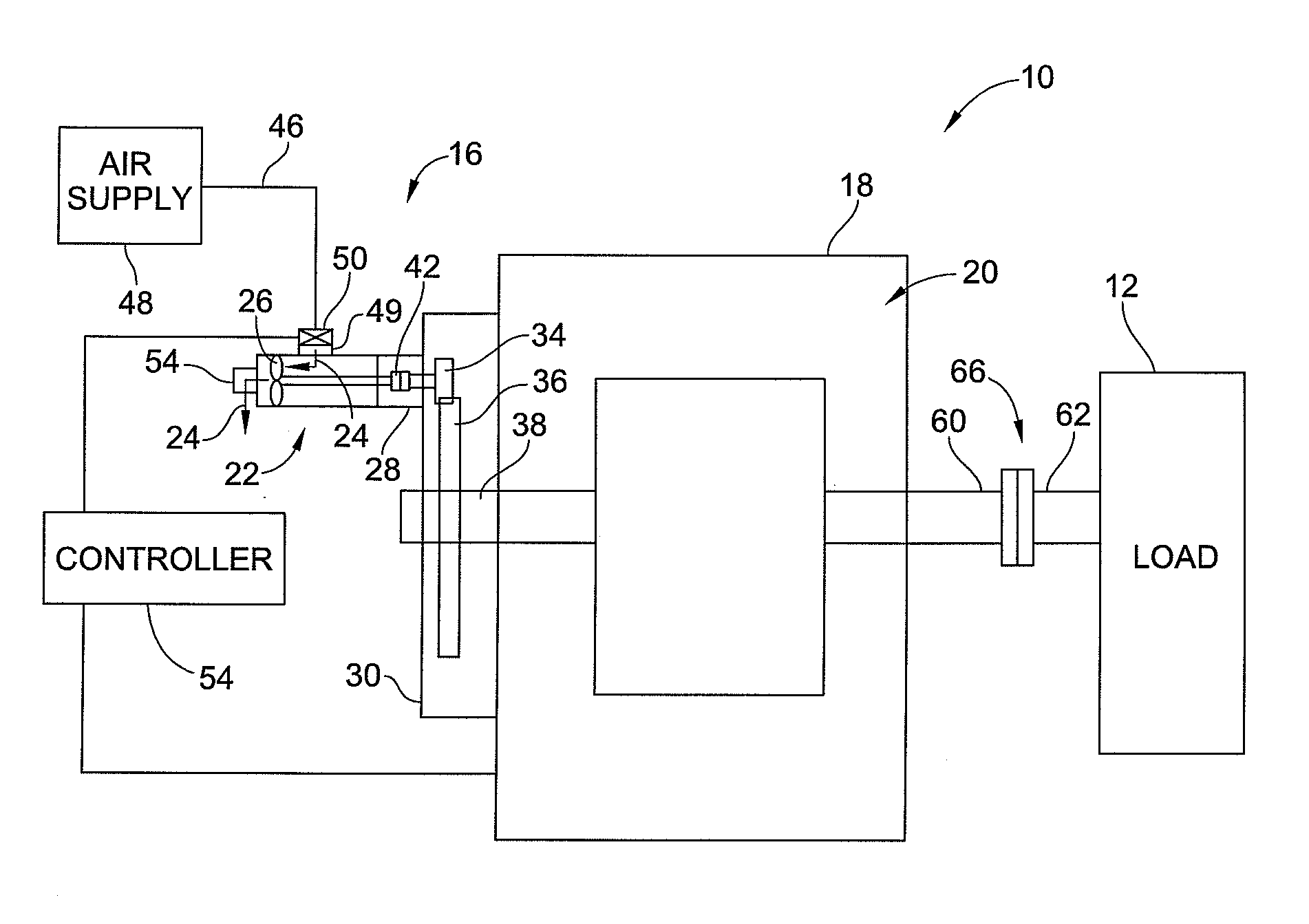
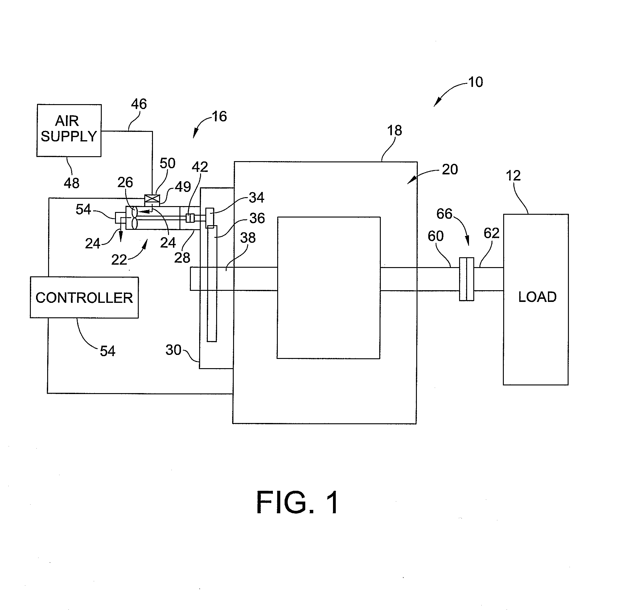
[0024]Referring to FIG. 1, shown in simplified form is an embodiment of a prime mover system 1O. The prime mover system 10 is operably coupled to and drives load 12. Load 12 can be any limiting load such as a compressor, a pump, a conveyor, a mill, grinder, etc. This list is not exhaustive or limiting and is provided by way of example only. The prime mover system 10 is an electric motor prime mover and includes an electric motor 18 for providing the motive power to drive load 12. As the prime mover system 10 includes electric motor 18 as the main source of motive power, the prime mover system 10 provides all of the ecological and maintenance benefits of an electricity based system. However, the embodiment of the prime mover system 10 beneficially eliminates many of the problems associated with using electric motor prime movers discussed previously. The prime mover system 10 eliminates or substantially reduces the problems associated with inrush currents and peak energy consumption d...


PUM


Abstract

An electric motor prime mover and method of starting an electric motor prime mover is provided. The prime mover includes an electric motor, a pneumatic motor and a mechanical coupling operably connecting the pneumatic motor to a rotor of the electric motor. The pneumatic motor initiates startup of the electric motor by driving the rotor of the electric motor prior to applying electrical power to the electric motor. After the rotor has attained sufficient rotational speed electricity is applied to the electric motor to drive the rotor. The use of the pneumatic motor allows the rotor to be rotating as electricity is initially applied to the electric motor preventing or substantially reducing inrush currents.

Description

FIELD OF THE INVENTION[0001]This invention generally relates to prime movers and more particularly to devices for assisting startup of electric motor prime movers.BACKGROUND OF THE INVENTION[0002]In today's industry, prime movers are used to provide motive power for operating other machines or mechanical systems. Typical prime movers include reciprocating combustion engines (gas and diesel), combustion gas turbines engines or electric motors. Reciprocating combustion engines and combustion gas turbine engines use fossil fuels and generate harmful exhaust emissions and many other by-products of combustion. With stricter government regulations on emissions and pollutants, ever increasing and volatile fissile fuel costs, the use of fossil fuel based prime movers are becoming less and less attractive. Besides pollution, exhaust emissions and costs of fuel, reciprocating engines and gas turbines generate sound pollution making them additionally difficult to employ proximate to communitie...

Claims


Application Information

Patent Timeline
Patent Type & Authority Applications(United States)
IPC IPC(8): H02P1/04H02K7/10H02K7/118H02K7/18
CPCH02K7/118H02P1/04
Inventor DIPASQUALE, JR., CHARLES
Owner SMITHS AEROSPACE INC
Why Eureka
Try Eureka