Sealing apparatus having sequentially engageable seals

a sealing apparatus and seal technology, applied in the direction of waterborne vessels, vessel construction, propellant elements, etc., to achieve the effect of preventing unnecessary wear and facilitating sequential deploymen

Inactive Publication Date: 2008-04-08
ASHBRIDGE & ROSEBURGH
View PDF25 Cites 9 Cited by
  • Summary
  • Abstract
  • Description
  • Claims
  • Application Information

AI Technical Summary

Benefits of technology

[0012]The present disclosure provides a sealing apparatus that includes a plurality of seal members, each seal member typically including a seal lip for engaging a moving member, e.g., a reciprocating or rotating shaft. In the event an initial seal member becomes worn or malfunctions, the disclosed sealing apparatus facilitates sequential deployment of additional seal member(s) to replace and / or supplement the previously engaged seal lip that is worn or malfunctioning. In a preferred embodiment of the present disclosure, the sealing apparatus includes an automatic mechanism for sequentially deploying the seal members. The disclosed sealing apparatus ensures that the back-up seal members are only deployed against the shaft, which may be rotating or reciprocating, or against an associated shaft sleeve, when needed, to prevent unnecessary wear on the seal lips during the period of time when no back-up / replacement / supplementary sealing is required.
[0013]According to a first preferred aspect of the present disclosure, a plurality of seal members, e.g., lip seals or seal rings, are arranged spaced apart along an axis of a shaft. The seal members are mounted to a stationary housing or cartridge and extend radially toward the shaft. The seal members include a first lip seal and one or more back-up lip seals. The shaft may optionally include a shaft sleeve fixed to the shaft. A barrier member, e.g., a barrier sleeve, is initially interposed between the shaft (or shaft sleeve) and the back-up lip seal(s). When desired, e.g., when leakage is observed, the barrier sleeve may be shifted outwardly in an axially direction to sequentially release the back-up lip seals, each released back-up lip seal assuming a radial length to be sealingly pressed to or against the outer circumference of the rotating or reciprocating shaft (or shaft sleeve). The previously deployed seal, or seals, remain applied to the shaft, even though spent, thus providing some limited, preliminary sealing effect which can serve, due to the pressure drop caused by each such spent seal, to make easier and thus prolong the life of the most recently released seal.

Problems solved by technology

The previously deployed seal, or seals, remain applied to the shaft, even though spent, thus providing some limited, preliminary sealing effect which can serve, due to the pressure drop caused by each such spent seal, to make easier and thus prolong the life of the most recently released seal.

Method used


Image

  • Sealing apparatus having sequentially engageable seals
  • Sealing apparatus having sequentially engageable seals
  • Sealing apparatus having sequentially engageable seals

Examples


first embodiment

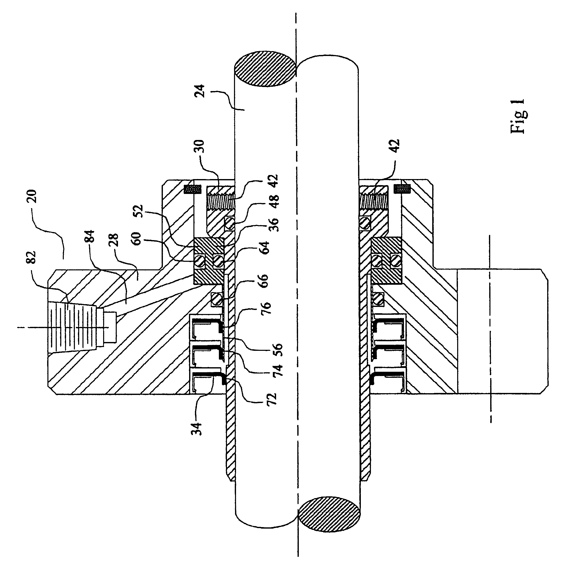
[0081]FIG. 6 illustrates an alternative embodiment according to the present disclosure. The sealing apparatus 120 is identical to the first exemplary embodiment described hereinabove, i.e., sealing apparatus 20, except as noted in the description and / or the figures. The apparatus 120 is depicted in a preassembly, non-operating condition. In this alternative exemplary embodiment, a barrier sleeve 136 includes an outer O-ring 60, but not the inner O-ring 64 of the An alternate gland 128 includes an inner O-ring 130 that can be sealed against an outer surface 132 of the shaft sleeve 30, when the shaft sleeve is in the retracted position as shown in FIG. 10. The gland 128 includes one or more threaded stop pins 142 threaded through an annular wall 143 of the gland 128, and a stop ring 144.

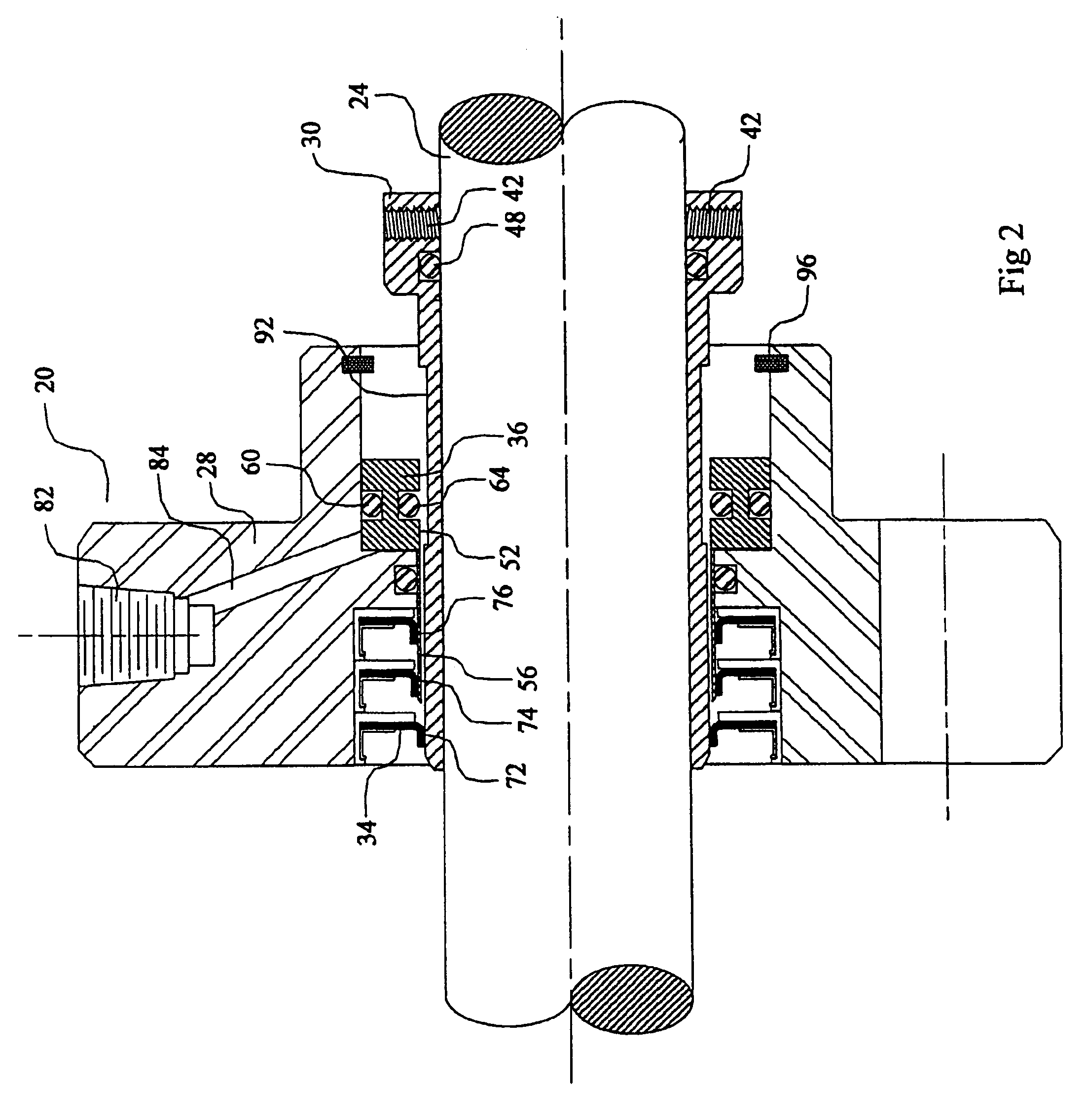
[0082]FIG. 7 illustrates the sealing apparatus 120 in the assembled operating condition with the shaft sleeve 30 extending outwardly (to the right) to be secured to the shaft (not shown). The O-ring 1...

embodiment 400

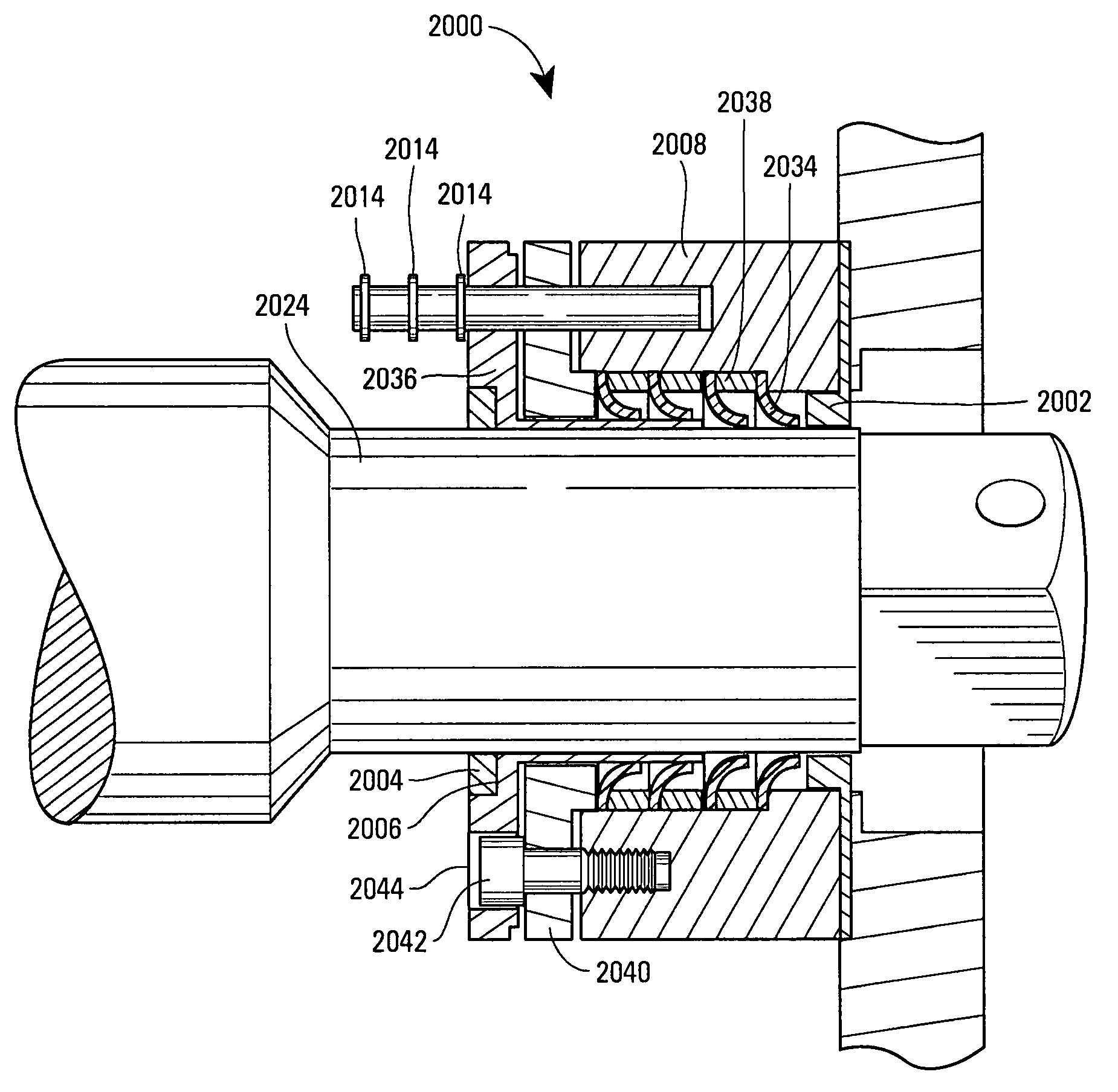
[0092]FIG. 18 illustrates a further alternate embodiment of the present disclosure, wherein sealing apparatus 400 surrounds a shaft sleeve 401 fixed on a shaft 24, shown in a pre-assembled, non-operating condition. The sealing apparatus 400 of this further exemplary embodiment is similar to the previously described embodiments, except as noted in the description and / or the figures. The sealing apparatus 400 includes a gland 420 holding a seal lip cluster 426, having four lip seals 428, 430, 432, 434. This embodiment 400 is similar to the embodiment of FIGS. 6-9, except that an annular channel 440 is arranged between the second and third lip seals 430, 432. Annular channel 440 is connected to a radial channel 442 and a port 444, and is used to input flushing, cooling, lubricating and / or barrier fluid between the second and third lip seals 430, 432. Likewise, an annular channel 450, a radial channel 452 and a port 454 are provided between the third and fourth lip seals 432, 434, and u...


PUM


Abstract

Advantageous seal systems are provided that include a barrier member movable relative to a shaft to allow sequential engagement of resilient seal members, e.g., lip seals, with the shaft. Movement of the barrier member may be effected manually or through introduction of pressurized fluid to effect piston-like movement. The disclosed seal assemblies may include an automatic leak detector and may utilize such leak detection to effectuate automatic movement of the barrier member. The barrier member may be moved relative to the shaft while the shaft is in movement, e.g., rotating or reciprocating, thereby permitting seal maintenance without interruption in operation. As seal members are sequentially brought into sealing engagement with the shaft, the previously engaged seal members contribute to the sealing performance of the seal assembly, although no longer effective to establish a stand-alone seal with the shaft. Front and rear bushings may be provided within the seal system.

Description

CROSS REFERENCE TO RELATED APPLICATIONS[0001]The present application is a Continuation-in-Part of U.S. patent application Ser. No. 10 / 312,020, filed Dec. 20, 2002, now issued as U.S. Pat. No. 6,979,002, which was the United States national stage under 35 U.S.C. § 371 of International application No. PCT / IB01 / 00621 having an international filing date of Apr. 13 2001, and the present application further claims priority to, and the benefit of, the following four applications: GB 0013481.4, filed Apr. 13, 2000; GB 0013480.9, filed May 4, 2000; U.S. Provisional Application No. 60 / 232,148, filed Sep. 9, 2000; and U.S. Provisional Application No. 60 / 241,497, filed Oct. 18, 2000.BACKGROUND OF THE DISCLOSURE[0002]1. Technical Field[0003]The present disclosure relates to advantageous seal systems having sequentially engageable seals, and more particularly to replacement seal systems that provide sequential engagement of lip seal members with moving element(s), e.g., rotating and / or reciprocat...

Claims


Application Information

Patent Timeline
Patent Type & Authority Patents(United States)
IPC IPC(8): F16J15/32F16J15/00
CPCB63H23/321F16J15/008Y10S277/914
Inventor RAMSAY, THOMAS W.
Owner ASHBRIDGE & ROSEBURGH
Why Eureka
Try Eureka