Shovel

a shovel and blade technology, applied in the field of shovels, can solve the problems of increasing the difficulty of the blade portion of the shovel to penetrate the material, the difficulty of the operator to both continue to penetrate the material and and the difficulty of the operator to extract the blade from the material. the effect of less operation force, easy penetration and less stress on the operator

Active Publication Date: 2013-05-16
CEJA LOUIS
View PDF5 Cites 6 Cited by
  • Summary
  • Abstract
  • Description
  • Claims
  • Application Information

AI Technical Summary

Benefits of technology

[0007]The unique design of the improved shovel exhibits a number of advantages. The teeth of the shovel focus force applied to the blade by an operator so as to allow for easier penetration by the shovel into material. By requiring less force to operate than a traditional shovel, the improved shovel alleviates stress to the operator.
[0008]The teeth and ribs further break apart solid material as the blade penetrates deeper into material thereby relieving friction and suction forces that act on traditional blades. Thus less overall effort need be expended by an operator while manipulating the improved shovel. The relatively thick teeth further prevent unnecessary wear to the thin blade. The thicker teeth provide a primary point of impact against material and prevent the thin blade from being ground down or damaged by hard or abrasive material, such as gravel, asphalt or concrete, when the shovel is used to scrape and / or penetrate such material, thereby adding to the longevity of the tool.
[0009]The toothed blade also provides the added benefit of operating in a multipurpose manner. The teeth provide added leverage for wedging, prying and lifting debris, allowing for an operator to separate material that is stuck together, such as separating tile from a floor or ice from a sidewalk. The flat blade is designed to marry to other flat surfaces, such as floors or sidewalks so as to slide smoothly along such surfaces without gouging and marring the surfaces as can easily occur when operating a traditional rounded shovel blade or thinly tined pitchfork. Also the teeth on the ends of the shovel blade, by protruding beyond the edge of the wide, flat blade enable the improved shovel to access tight spaces.

Problems solved by technology

The problem with the aforementioned shovels is that the blade portion of the shovel is difficult to push into material.
As the shovel blade progresses into the material, an increasing amount of blade surface comes into contact with the material creating friction, making it increasingly harder for an operator to penetrate the material.
Additionally, because the shovel blades are of substantially uniform thickness, a suction may be created between the blade and the material making it difficult for the operator to both continue to penetrate the material and extract the blade from the material.

Method used


Image

  • Shovel
  • Shovel
  • Shovel

Examples


Embodiment Construction

[0014]The preferred embodiments of the present invention are described with reference to the drawings below. In the drawings, like numbers are used to refer to like elements. The following is a description of the preferred embodiment of the present invention.

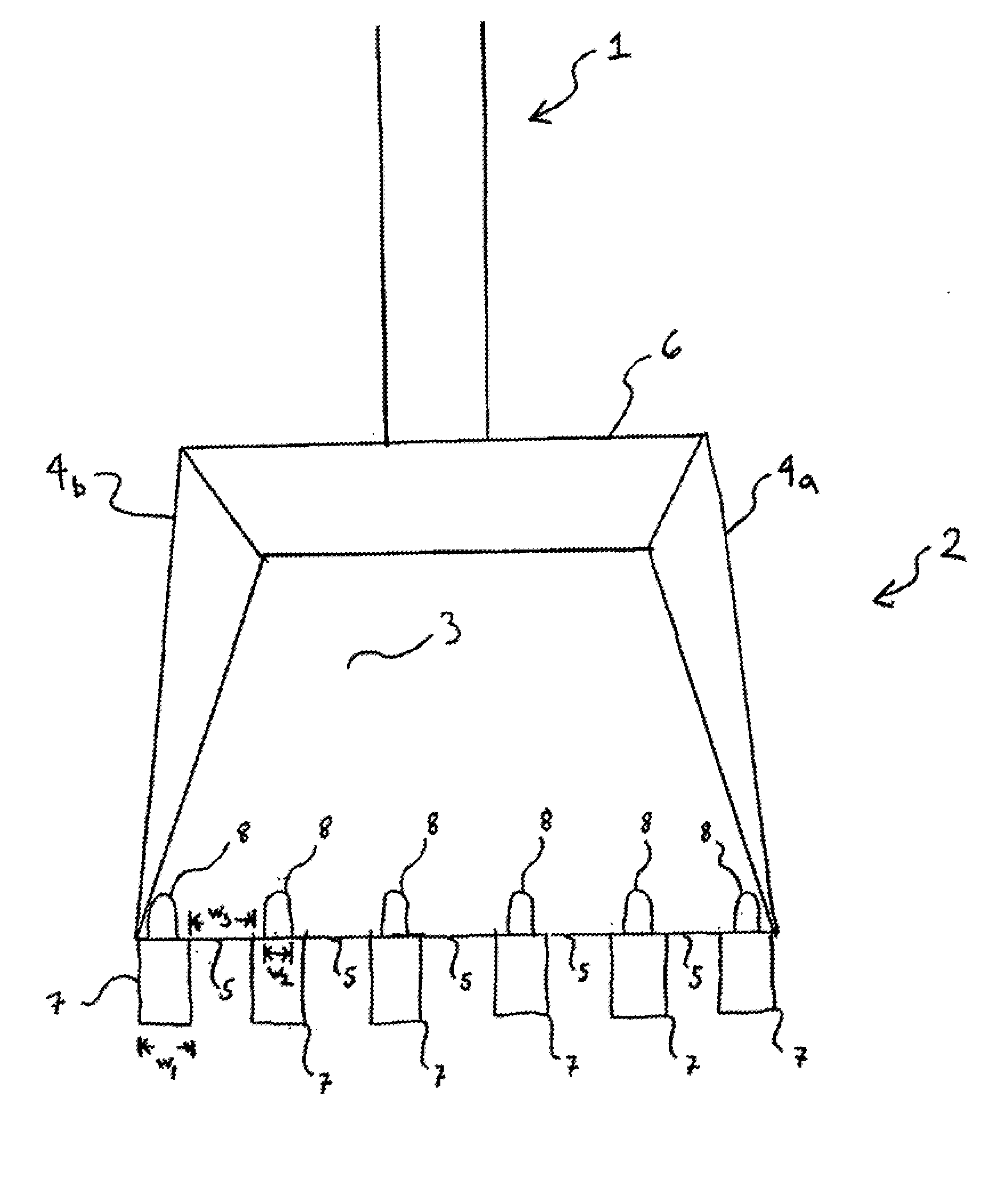
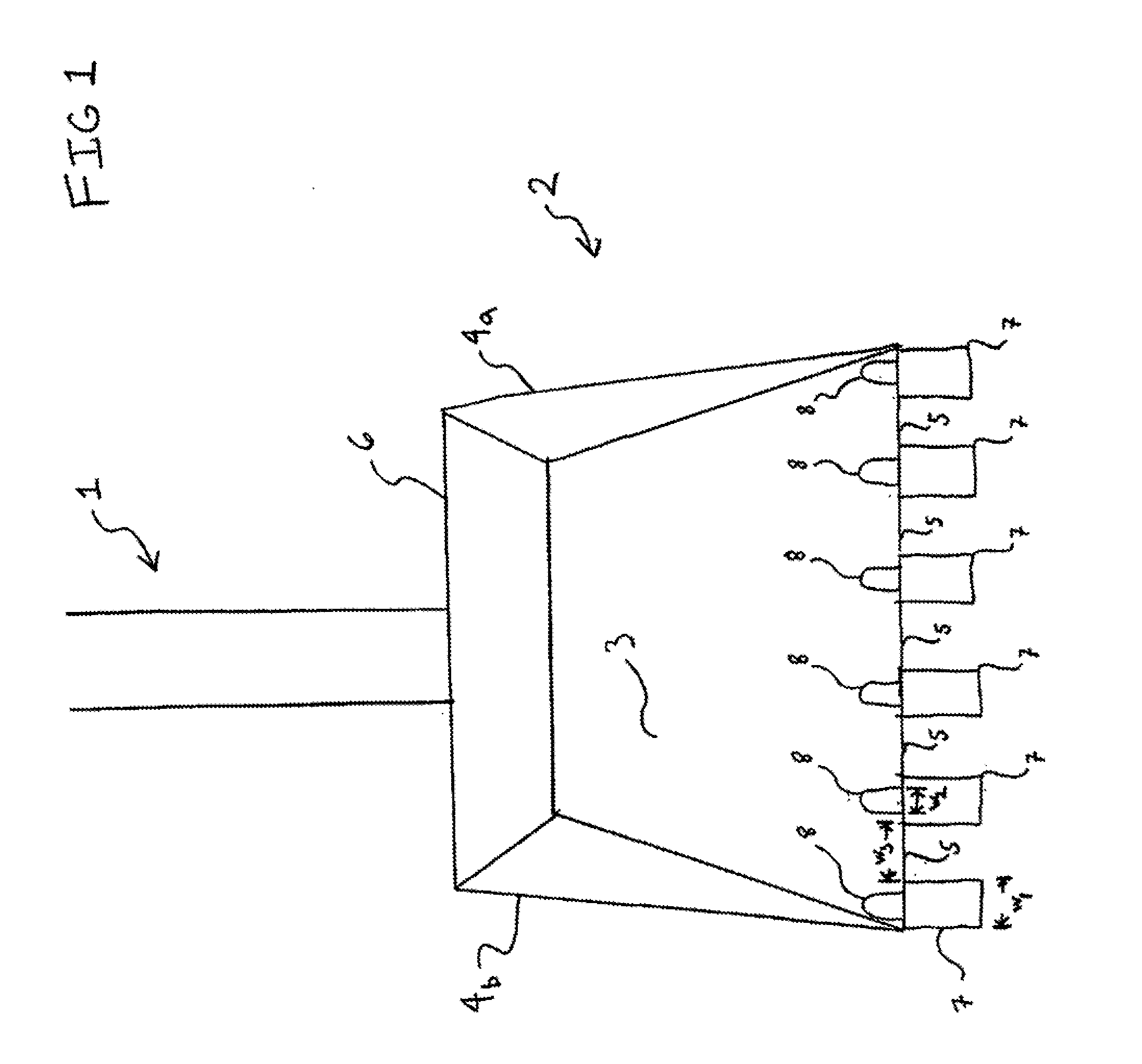
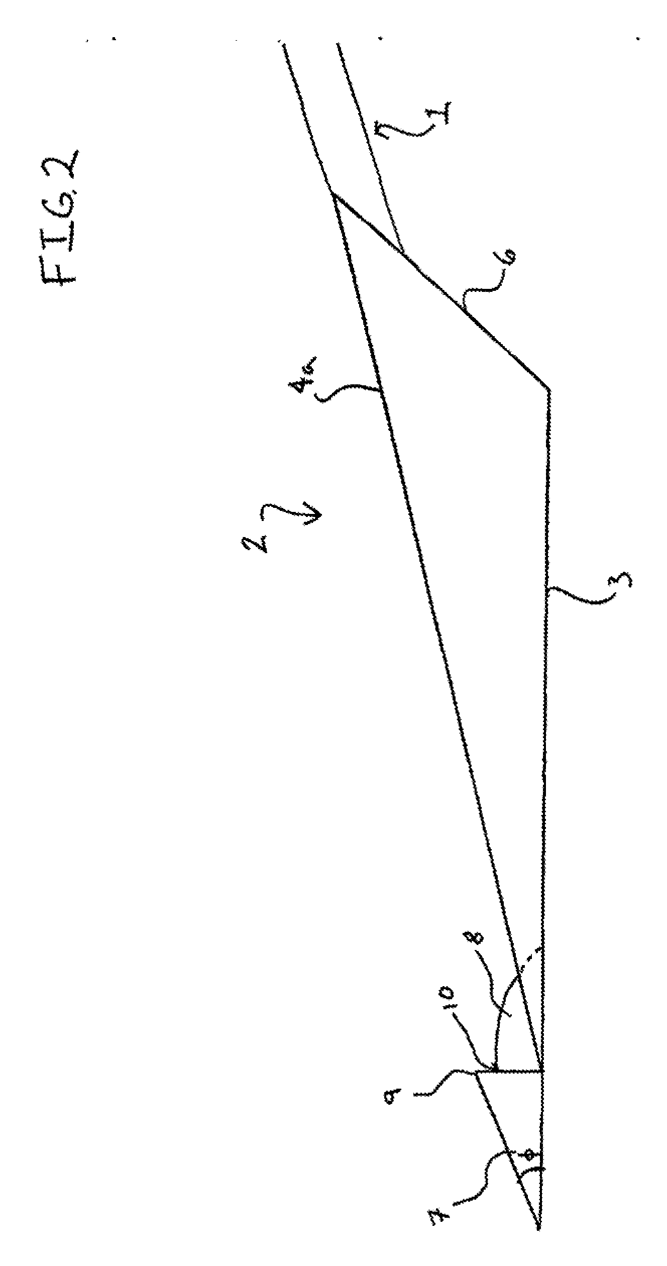
[0015]Referring to FIG. 1, the improved shovel is made of two parts, a handle 1 and a blade 2. As shown in FIG. 1, the blade is generally square in shape, having base plate 3 a first side 4a and a second side 4b, a front edge 5, and a back 6. The handle 1 of the shovel is connected to the back portion 6 of the blade 2 such that an operator may apply force to the handle and thereby manipulate the blade of the shovel. Additionally, a number of teeth are connected to the blade of the shovel. Each tooth 7 is connected to the front edge of the blade.

[0016]Because the profile of the front edge is preferably thin, on the order of 0.0625-0.125 inches for example, there is very little material to provide a connection between the teeth an...


PUM


Abstract

A manually operated shovel having a blade and a plurality of tooth members is provided. The tooth members of the shovel provide individual points of contact between the shovel blade and material, such as earth, when the blade of the shovel is pressed into the material. The tooth members provide a mechanical advantage that focuses the pressure applied to the shovel by the operator so as to penetrate material more easily than traditional uniformly bladed shovels.

Description

CROSS-REFERENCE TO RELATED APPLICATION:[0001]This application claims priority to U.S. Provisional Application Ser. No. 61 / 558,186 filed Nov. 10, 2011, the entirety of which is incorporated herein by this reference.FIELD OF INVENTION[0002]The present invention generally relates to an improved shovel design. Specifically, the invention includes a plurality of tooth members extending from the blade portion of the shovel. The invention is designed easily manually manipulated by an individual and may be used in a variety of applications such as digging in earth or snow as well as others.BACKGROUND OF THE INVENTION[0003]Manually operated shovels for digging in and moving earth and snow are widely used. In the past, shovels generally included a broad blade and a handle extending from the blade. Some shovel blades included a substantially flat blade portion that terminated in squared edge, others included a slightly curved blade portion that tapered from a wide section to a triangular point...

Claims


Application Information

Patent Timeline
Patent Type & Authority Applications(United States)
IPC IPC(8): A01B1/04E01H5/02
CPCE01H5/02A01B1/04
Inventor CEJA, LOUIS
Owner CEJA LOUIS
Why Eureka
Try Eureka