Vent Member and Vent Structure

a technology of vent structure and vent member, which is applied in the direction of ventilation system, electrical apparatus casing/cabinet/drawer, container preventing decay, etc., can solve the problems of not always the case, and achieve the effect of maintaining gas permeability, preventing water droplets, and maintaining gas permeability

Inactive Publication Date: 2010-09-09
NITTO DENKO CORP
View PDF8 Cites 27 Cited by
  • Summary
  • Abstract
  • Description
  • Claims
  • Application Information

AI Technical Summary

Benefits of technology

[0011]In the vent member (or the vent structure) of the present invention described above, the height from the outer surface of the housing to the opening end face on the opposite side sufficiently is ensured as 4 mm or more. This makes it possible to prevent water droplets or the like from flowing onto the gas permeable membrane even when water droplets or the like remain in areas including a connection point between the vent member and the housing. In other words, it is possible to obtain a vent member that can maintain gas permeability in a reliable manner even when water droplets or the like adhere to the outer surface of the housing.
[0012]In the vent member (or the vent structure) of another aspect of the present invention, the support body, to which the gas permeable membrane is fixed, includes the base portion having a lateral cross-sectional area increasing continuously or stepwise toward the housing. According to such a structure, it becomes difficult for water droplets or the like to remain around the border between the vent member and the housing. As a result, it is possible to obtain a vent member that can prevent water droplets or the like from flowing onto the gas permeable membrane even when the water droplets or the like adhere to the outer surface of the housing, and thereby can maintain gas permeability in a reliable manner.

Problems solved by technology

However, intensive studies made by the inventor have found that this is not always the case.

Method used


Image

  • Vent Member and Vent Structure
  • Vent Member and Vent Structure
  • Vent Member and Vent Structure

Examples


first embodiment

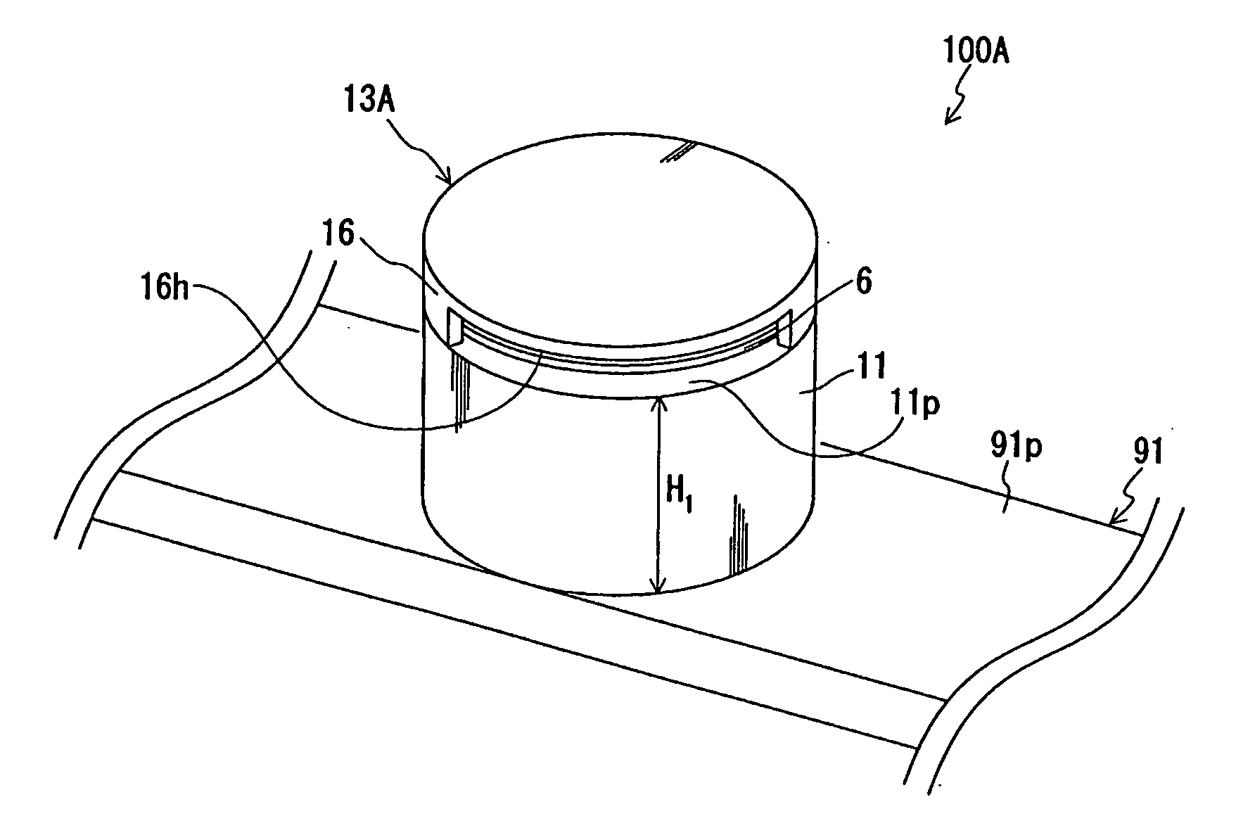
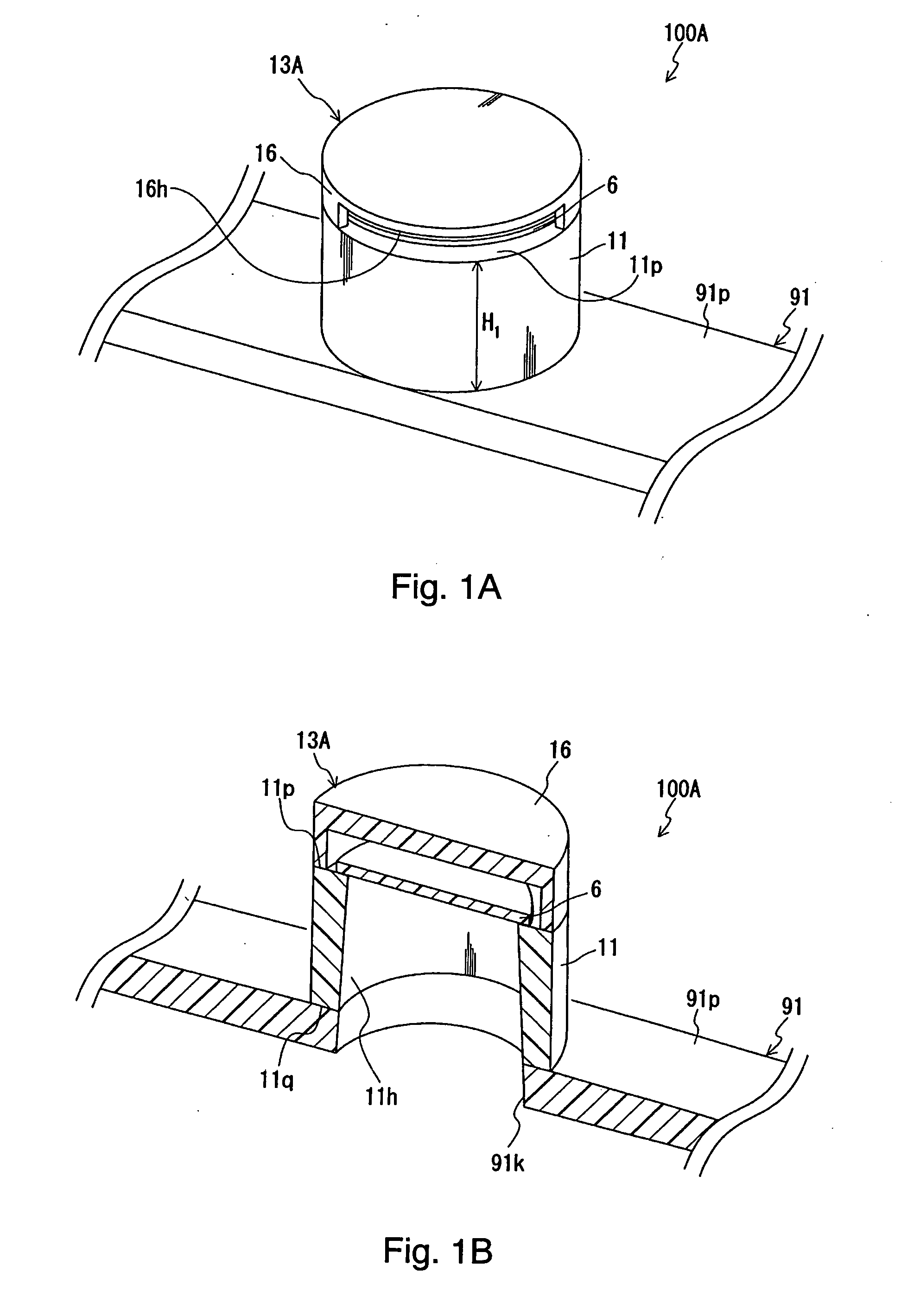
[0043]Hereinafter, embodiments of the present invention will be described with reference to the attached drawings. FIG. 1A is a perspective view of a vent member of a first embodiment according to the present invention, and FIG. 1B is a sectional perspective view thereof. FIG. 12 is a general view of a housing on which the vent member of FIG. 1A is attached. As shown in FIG. 12, the vent member 13A shown in FIGS. 1A and 1B constitutes a vent structure 100A for providing ventilation between the interior and the exterior of a housing 91 when attached to an opening portion 91k of the housing 91 of, for example, an automobile electrical component. The housing is not limited to a box-shaped housing as shown in FIG. 12. Any components or articles having an interior space that needs ventilation can be a housing to which the vent member of the present invention is to be attached.

[0044]As shown in FIGS. 1A and 1B, the vent member 13A is provided with a support body 11 having a through hole 1...

second embodiment

[0062]FIG. 3A is a perspective view of a vent member of a second embodiment, and FIG. 3B is a sectional perspective view thereof. A vent structure 102 for performing ventilation between the interior and the exterior of the housing 91 is constituted by attaching a vent member 23 shown in FIGS. 3A and 3B to the opening portion 91k of the housing 91.

[0063]The vent member 23 is provided with a support body 21 having a through hole 21h and 21i to serve as a gas passage between the interior and exterior of the housing 91 and the gas permeable membrane 6 fixed to the support body 21 so as to close the through hole 21h and 21i. A second opening end face 21q serves as a bonding surface that is directly bonded to the housing 91. The support body 21 includes a cover 26 covering the gas permeable membrane 6. A clearance between the gas permeable membrane 6 and the cover 26 communicates with an opening 26h that opens in a direction parallel to the in-plane of the gas permeable membrane 6. The ve...

third embodiment

[0068]A vent member 43A of a third embodiment shown in FIG. 4A is a modification of the vent member 23 of the second embodiment. A vent structure 106A is constituted by attaching the vent member 43A to the opening portion 91k of the housing 91. This embodiment is common with the embodiments above in that a through hole 41h and 41i is divided into an upper portion and a lower portion by the gas permeable membrane 6, a support body 41 includes a cover 46, and a height H7 from the outer surface 91p of the housing 91 to a first opening end face 41p is set to 4 mm or more. A difference is that the gas permeable membrane 6 is integrated with the support body 41 by insert molding.

[0069]As shown in FIG. 4A, the gas permeable membrane 6 is fixed to the support body 41 in the through hole 41h and 41i by integrating a peripheral portion 6k with the resin of which the support body 41 is composed. In other words, the peripheral portion 6k of the gas permeable membrane 6 is embedded into the supp...


PUM


Abstract

A vent structure 100A of the present invention includes a housing 91 and a vent member 13A attached to an opening portion 91k of the housing 91. The vent member 13A is provided with a support body 11 having a through hole 11h to serve as a gas passage between the interior and the exterior of the housing 91 and a gas permeable membrane 6 fixed to the support body 11 so as to close the through hole 11h. Assuming that a thickness direction of the gas permeable membrane is a height direction, a height H1 of the support body 11 from a second opening end face 11q (aligned with an outer surface 91p of the housing 91) to a first opening end face 11p on the other side is set to 4 mm or more.

Description

TECHNICAL FIELD[0001]The present invention relates to a vent member attached to a housing that accommodates automobile components, electronic components or the like. The present invention also relates to a vent structure using the vent member.BACKGROUND ART[0002]Housings that accommodate automobile electrical components such as lamps, sensors and ECUs (electronic control unit) have a vent member attached thereto to ensure ventilation between the interior and the exterior of the housing and to prevent foreign matter from intruding into the housing. One example of such a vent member is disclosed in JP 2004-47425A and JP 2003-336874A.[0003]A vent member disclosed in JP2004-47425A is, for example, provided with a support body 203 on which a gas permeable membrane 202 is disposed and a cover part 204 attached to the support body 203 so as to cover the gas permeable membrane 202, as shown in FIG. 13. The vent member 201 thus configured is fixed to an opening portion 207 of a housing 206 v...

Claims


Application Information

Patent Timeline
Patent Type & Authority Applications(United States)
IPC IPC(8): F24F7/00
CPCF21S48/335H05K5/0213F24F2003/1435F21V31/03F21S45/30H05K5/0215B60R16/02B65D81/26
Inventor FURUYAMA, SATORUYANAGI, TOSHIKI
Owner NITTO DENKO CORP
Why Eureka
Try Eureka