Paint can liner

a paint can and liner technology, applied in the field of paint can liner, can solve the problems of saving painter time and cost, and achieve the effect of eliminating the time spent in extra cleanup, saving painter time and cost, and being convenient to us

Inactive Publication Date: 2010-09-16
CRUDGINGTON JR CLEVELAND BENEDICT
View PDF2 Cites 15 Cited by
  • Summary
  • Abstract
  • Description
  • Claims
  • Application Information

AI Technical Summary

Benefits of technology

[0009]The present disclosure provides an effective and easy method for rolling out these smaller rollers directly over the paint can, thus eliminating the need for pouring paint into a separate pan. For a number of reasons this novel method will save the painter time and cost. Furthermore, an additional roller pan will no longer be required, paint lost drying in such a pan will be saved, and time spent in extra cleanup will be eliminated.

Problems solved by technology

For a number of reasons this novel method will save the painter time and cost.

Method used


Image

  • Paint can liner
  • Paint can liner
  • Paint can liner

Examples


Embodiment Construction

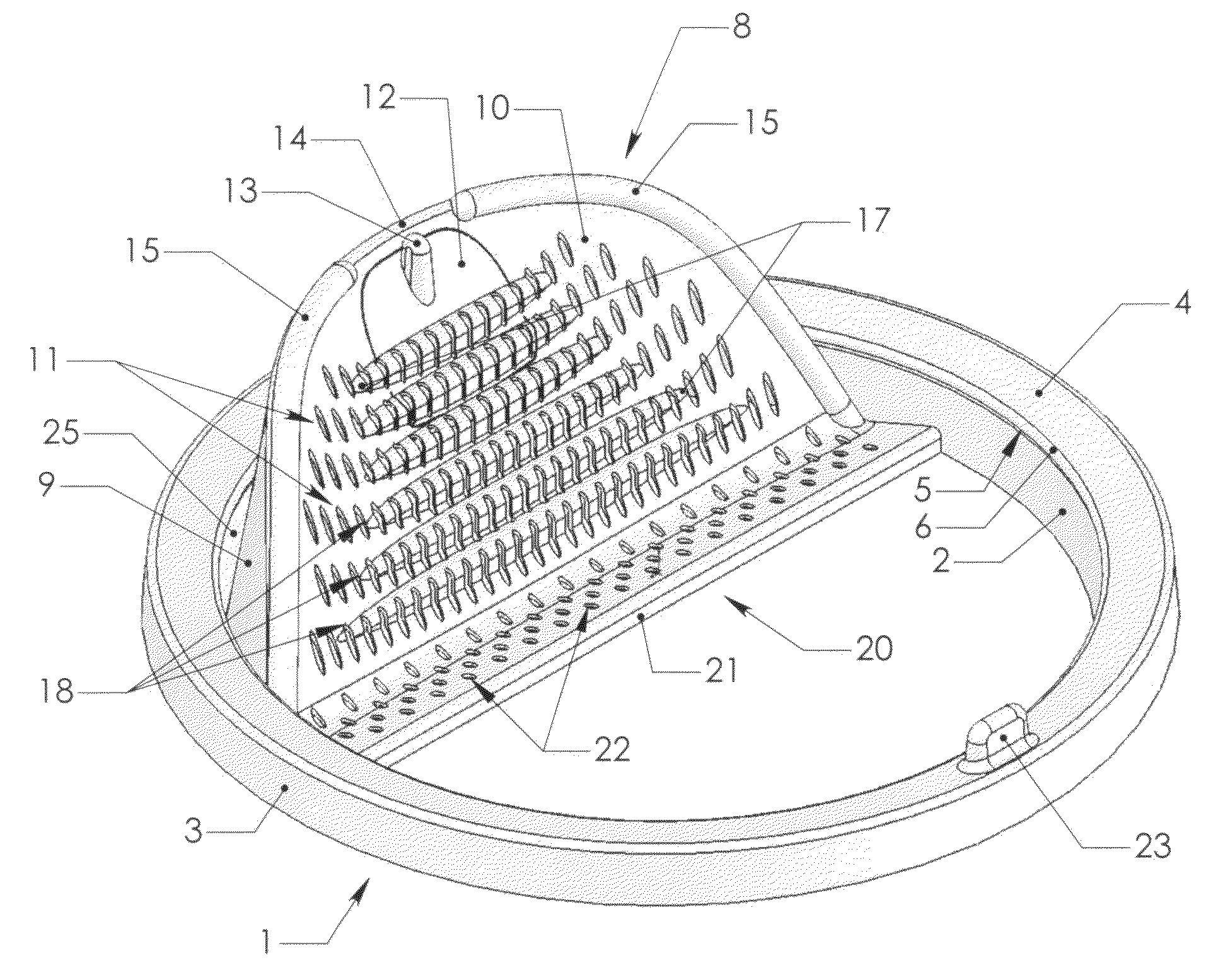
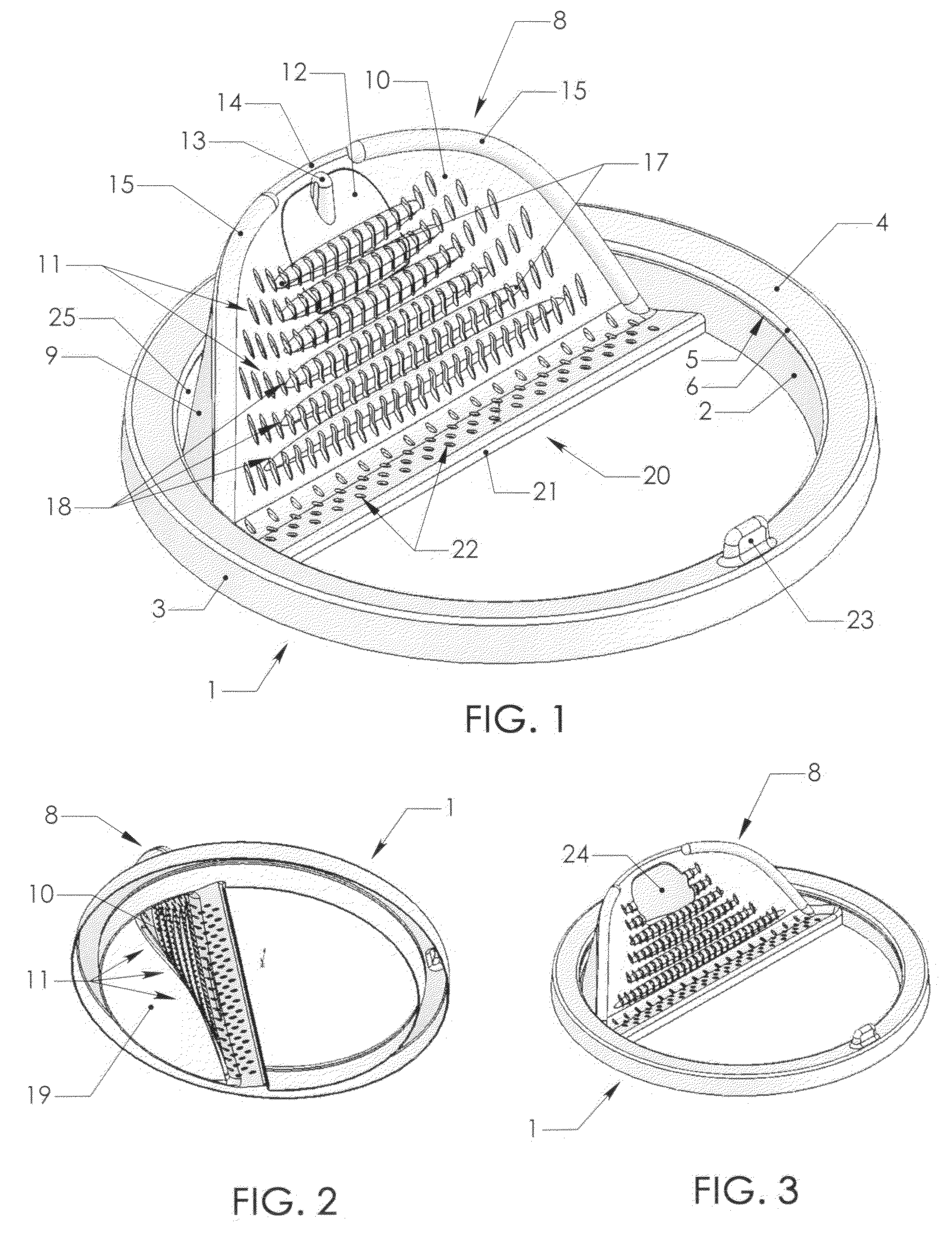
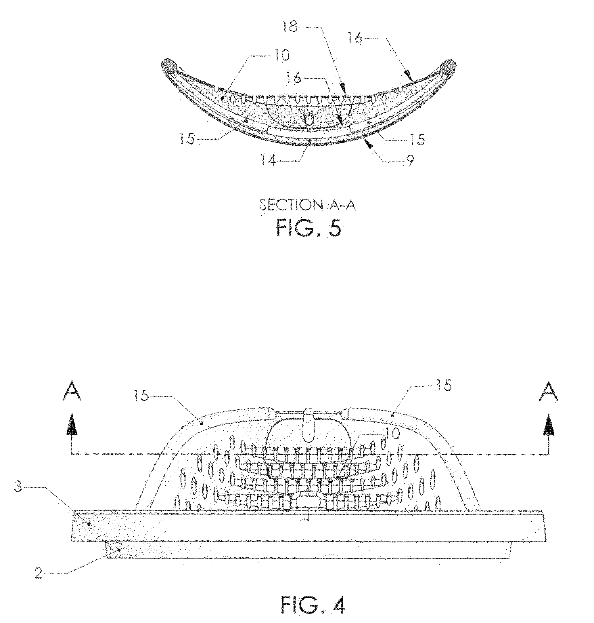
[0026]Depicted in FIG. 1 which is a fundamental embodiment common to all variations of the present disclosure, is the annular mounting ring 1 that affixes to the top of an open cylindrical paint can (not shown) either of plastic or metal. Since the sealing configuration for metal cans differs from those made of plastic, the mounting configuration likewise differs. For a Paint Can Liner specific to metal paint cans, the mounting ring 1 includes an annular top-wall 4 extending down into interior 2 and exterior 3 side-walls. An inwardly facing annular mounting groove 6 formed within the interior side-wall 2 permits the mounting ring 1 to become locked as well as sealed to the paint can.

[0027]The mounting mechanism is more clearly visualized by referring to the cross-sectional view, FIG. 7, which details the mounting portion applied to a metal paint can 30. In its preferred configuration, the mounting groove 6 is bounded by an annular mounting ridge 5 directly below and by the top-wall ...


PUM


Abstract

A multipurpose attachment for cylindrical cans containing paints, varnishes and the like, which snap-fit engages to the top of the open cans and having uniformly thin, structurally rigid, and singularly molded construction that is disposable. The paint can liner protects the can's sealing channel into which the lid of a metal can mates, and provides an array of benefits suitable for either metal or plastic paint cans. In its preferred embodiment, primarily for gallon or similarly sized containers, the liner includes a pouring spout, an optional filter for use while pouring, a ribbed sloping surface for rolling excess paint from mini rollers, a horizontal shelf for resting either mini roller or paintbrush, and a linear edge for wiping excess paint from brushes.

Description

[0001]PROVISIONAL PATENT APPLICATION 60 / 901,097 filed Feb. 12, 2007.U.S. PATENT DOCUMENTS1,952,288March 1934Saxon221 / 232,106,381January 1938Rough221 / 232,145,748January 1939Bailey221 / 232,471,189May 1949Bartels210 / 163.52,627,367February 1953Bork222 / 5702,646,193July 1953Best222 / 5702,767,891May 1955Beadles222 / 5702,720,346October 1955Compton222 / 5702,765,966October 1956Davis222 / 5703,074,604January 1963Baroud222 / 5693,102,667September 1963Ullevig222 / 5693,221,955December 1965Banaszak222 / 5693,239,113March 1966Knize222 / 5693,309,000March 1967Haverstick222 / 5703,400,867September 1968Giannone222 / 5703,469,735September 1969Burt220 / 6983,693,829September 1972Price222 / 6983,695,488October 1972Olsson222 / 5703,853,249February 1974Weir, Jr. et al.222 / 5704,009,802March 1977Haydechok222 / 1084,203,537May 1980McAlister222 / 5704,225,064September 1980Westcott222 / 570 X4,240,568December 1980Pool222 / 570 X4,316,560February 1982Carter222 / 5674,583,666April 1986Buck222 / 1094,907,714February 1989Gatz222 / 5704,949,884August 1...

Claims


Application Information

Patent Timeline
Patent Type & Authority Applications(United States)
IPC IPC(8): B65D25/00
CPCB44D3/128
Inventor CRUDGINGTON, JR., CLEVELAND BENEDICT
Owner CRUDGINGTON JR CLEVELAND BENEDICT
Why Eureka
Try Eureka