Roof bar for a motor vehicle

Inactive Publication Date: 2010-09-16
FORD GLOBAL TECH LLC
View PDF15 Cites 3 Cited by
  • Summary
  • Abstract
  • Description
  • Claims
  • Application Information

AI Technical Summary

Benefits of technology

[0008]According to a first aspect of the invention there is provided a stowable roof bar for a motor vehicle comprising an elongate load carrying member extending across the vehicle and being pivotally connected to a roof of the vehicle for movement between stowed and deployed positions. A latch mechanism selectively holds the elongate load carrying member in the deployed position in which a crossbar portion of the elongate load carrying member is spaced above the roof of the vehicle. The width of the crossbar portion is greater than the thickness of the crossbar portion and the crossbar portion is re-orientated by the movement of the elongate load carrying member from the stowed position to the deployed position so as to increase the vertical resistance to bending of the crossbar portion. This has the advantage that a thin crossbar portion can be used to reduce the stowed height without compromising the resistance to bending of the crossbar portion when the roof bar is deployed.
[0015]This has the advantage that the roof bar can be stowed or deployed from one side of the motor vehicle.
[0023]Each control link may be fastened at one end to a rod used to link the two latch mechanisms and is pivotally connected at an opposite end to one of the two stays, wherein a longitudinal displacement of the rod by a user of the vehicle is operable to simultaneously release both latch mechanisms and rotational movement of the rod facilitates folding of the roof bar.

Problems solved by technology

It is a problem with a removable roof bar that considerable time and effort is required to fit or remove the roof bar from the vehicle.
It is a further problem that such fixed but removable roof bars greatly increase the height of the vehicle when they are fitted and, as such, removable roof bars are not ideal for use on a light commercial vehicle such as a van where it is desirable to keep the height of the vehicle below the height restrictions commonly imposed at car park entrances when no load is to be carried on the roof.

Method used


Image

  • Roof bar for a motor vehicle
  • Roof bar for a motor vehicle
  • Roof bar for a motor vehicle

Examples


Embodiment Construction

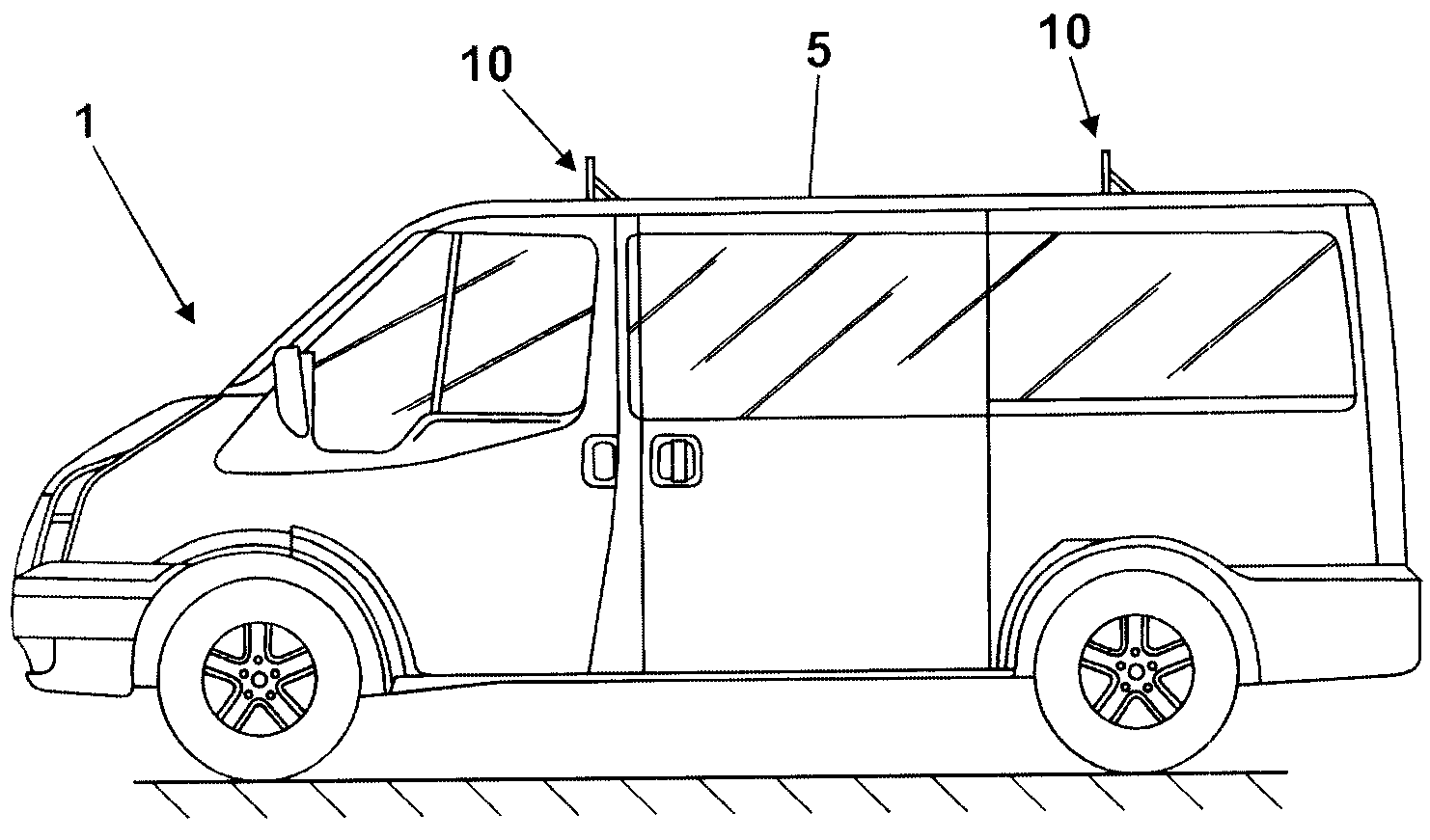
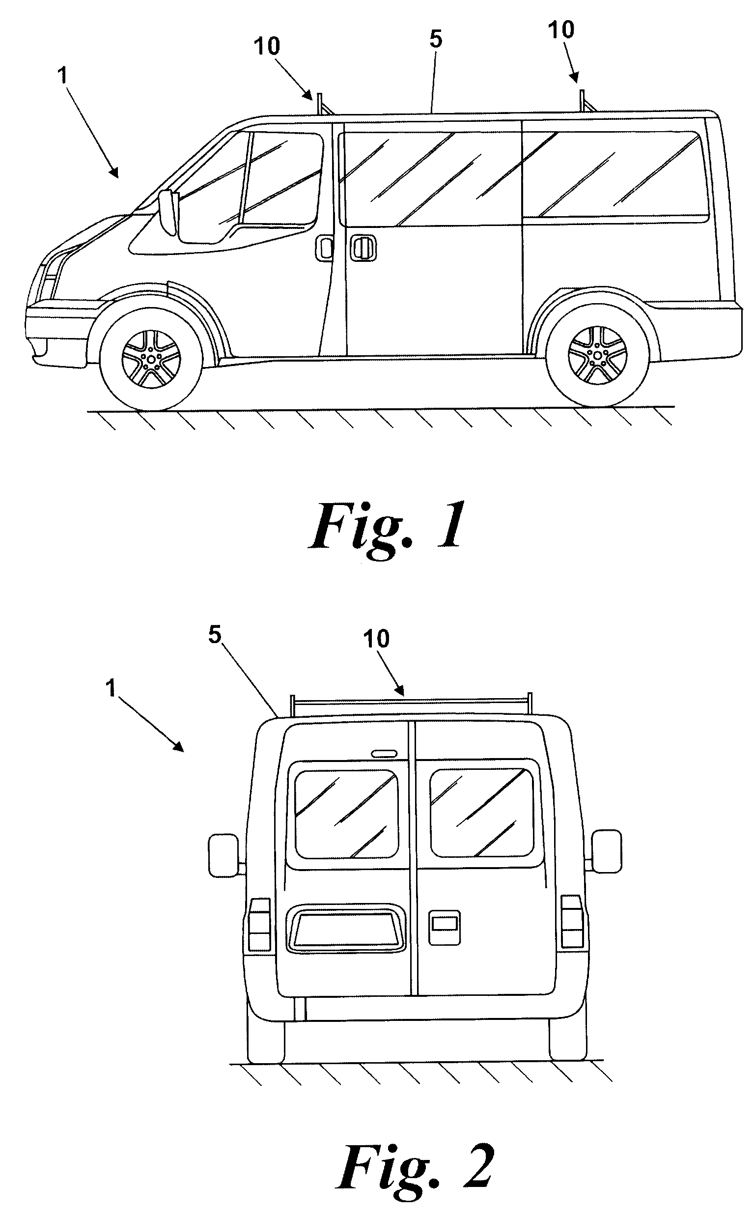
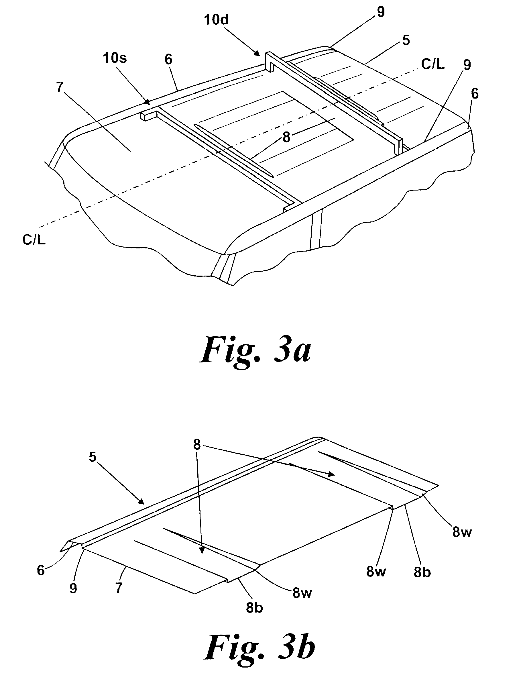
[0049]FIGS. 1 to 4b show motor vehicle 1 as having roof 5 upon which is mounted two spaced apart identical stowable roof bars, 10.

[0050]Each of the roof bars 10 is reversibly moveable between a stowed state, indicated by the reference numeral 10s on FIG. 3a, to a deployed state, indicated by the reference numeral 10d on FIG. 3a, where it is retainable by a latch mechanism.

[0051]In FIGS. 1 to 3a the motor vehicle is in the form of a van 1 and is shown with two roof bars 10 fitted to its roof 5 but it will be appreciated that more than two roof bars 10 could be fitted to the roof 5.

[0052]Roof 5 comprises a convex central portion, 7, bounded on each longitudinal side by a drainage ditch, 9, two channels 8 each having sides surfaces 8w and a base surface 8b and a ridge 6 running longitudinally along both outer edges of the roof 5.

[0053]Referring now to FIGS. 4a and 4b, the central roof portion 7 has a high point or crown located on the center line C / L of motor vehicle 1 and, in this cas...


PUM


Abstract

A roof bar (10) for a motor vehicle (1) includes an elongate load carrying member (13) selectively held in a deployed position by a latch mechanism (20). A crossbar portion (15) of the elongate load carrying member (13) is wider than it is thick and is orientated such that the width of the crossbar portion (15) is vertically arranged when the roof bar (10) is in the deployed position so as to increase the resistance to vertical bending of the crossbar portion (15).

Description

CROSS REFERENCE TO RELATED APPLICATIONS[0001]None.BACKGROUND OF THE INVENTION[0002]1. Field of the Invention[0003]This invention relates to a motor vehicle, and in particular to a roof bar for carrying a load on a roof of the motor vehicle.[0004]2. Related Art[0005]It is known to provide a motor vehicle with two or more removable roof bars in order to carry objects on the roof of a motor vehicle such as, for example, a roof box, a ladder, scaffold poles, scaffold planks and long lengths of timber. It is a problem with a removable roof bar that considerable time and effort is required to fit or remove the roof bar from the vehicle.[0006]It is a further problem that such fixed but removable roof bars greatly increase the height of the vehicle when they are fitted and, as such, removable roof bars are not ideal for use on a light commercial vehicle such as a van where it is desirable to keep the height of the vehicle below the height restrictions commonly imposed at car park entrances ...

Claims


Application Information

Patent Timeline
IPC IPC(8): B60R9/045B60R9/052
CPCB60R9/045
Inventor GERHARDT, TORSTENHARDING, JOHN K.FLEMING, STEVE DAVIDSTANESBY, DANNY EDWARDAGIUS, ALICIAFARRELLY, WILLWRIGHT, IAN SUTHERLAND
Owner FORD GLOBAL TECH LLC
Why Eureka
Try Eureka