Thermal head

a head and heat dissipation technology, applied in the field of thermal heads, can solve the problems of low joint strength between the head substrate and the heat dissipation member, etc., to enhance the power saving effect of the thermal head, and prevent excessive heat dissipation of heat from the heating elements.

Inactive Publication Date: 2010-09-16
ALPS ALPINE CO LTD
View PDF4 Cites 4 Cited by
  • Summary
  • Abstract
  • Description
  • Claims
  • Application Information

AI Technical Summary

Benefits of technology

[0013]In a thermal head according to an example, the surface of the heat dissipation member is provided with the heat accumulation adjusting groove having a recessed shape along the arrangement direction of the row of the heating elements, so that air in the heat accumulation adjusting groove of the heat dissipation member functions as an insulating material, thereby preventing excessive heat dissipation from the heating element to the heat dissipation member. Also, the heat dissipation member is formed so that both edge portions of the surface of the heat dissipation member in the width direction of the heat accumulation adjusting groove come in contact with the rear surface of the head substrate, so that the head substrate can be stably supported by the heat dissipation member, and heat from the heating elements is transferred to the heat dissipation member from the portions of the surface of the heat dissipation member which come in contact with the head substrate, thereby properly dissipating the heat from the heating element by the heat dissipation member.
[0014]In addition, the heat accumulation adjusting groove may be disposed at a position such that a widthwise interval between a center of the heat accumulation adjusting groove in the width direction thereof and a center of the heating element in a width direction thereof is equal to or less than approximately 0.5 mm. Accordingly, a heat accumulation effect can be exhibited by the heat accumulation adjusting groove, thereby further enhancing the power saving effect of the thermal head.
[0015]In addition, the heat accumulation adjusting groove may be formed to have a width in the range of approximately 20 to 80% of a width of the head substrate. As described above, the heat accumulation adjusting groove is formed so that the width thereof is equal to or greater than approximately 20% of the width of the head substrate, so that excessive dissipation of the heat from the heating elements by the heat dissipation member can be prevented, thereby further enhancing the power saving effect of the thermal head. Moreover, the heat accumulation adjusting groove is formed so that the width thereof is equal to or smaller than approximately 80% of the width of the head substrate, so that it is possible to obtain a recorded image with good image quality during recording. Furthermore, it is possible to prevent a contact area of the head substrate and the heat dissipation member from being too small, so that it is possible to reliably prevent the head substrate from separating from the heat dissipation member without degrading the shear strength of the head substrate and the heat dissipation member. Therefore, it is possible to stably support the head substrate by the heat dissipation member.
[0016]As described above, in the thermal head according to the examples disclosed herein, heat from the heating elements can be properly dissipated by the heat dissipation member, and excessive heat dissipation can be prevented. Accordingly, it is possible to achieve improvements in the heat dissipation characteristics and the power saving effect and stably support the head substrate provided with the heating elements by the heat dissipation member.

Problems solved by technology

Therefore, there is a concern that the heat from the heating elements is excessively dissipated.
As a result, there is a concern that the heat from the heating elements is excessively dissipated.
However, since the head substrate is cantilevered by the heat dissipation member, joint strength between the head substrate and the heat dissipation member is low, and accordingly, as pressure is applied to the head substrate during recording, there is a problem in that the head substrate and the heat dissipation member may be separated from each other.

Method used


Image

  • Thermal head
  • Thermal head
  • Thermal head

Examples


Embodiment Construction

[0023]The following description is intended to convey a thorough understanding of the embodiments described by providing a number of specific embodiments and details involving thermal heads. It should be appreciated, however, that the present invention is not limited to these specific embodiments and details, which are exemplary only. It is further understood that one possessing ordinary skill in the art, in light of known systems and methods, would appreciate the use of the invention for its intended purposes and benefits in any number of alternative embodiments, depending on specific design and other needs.

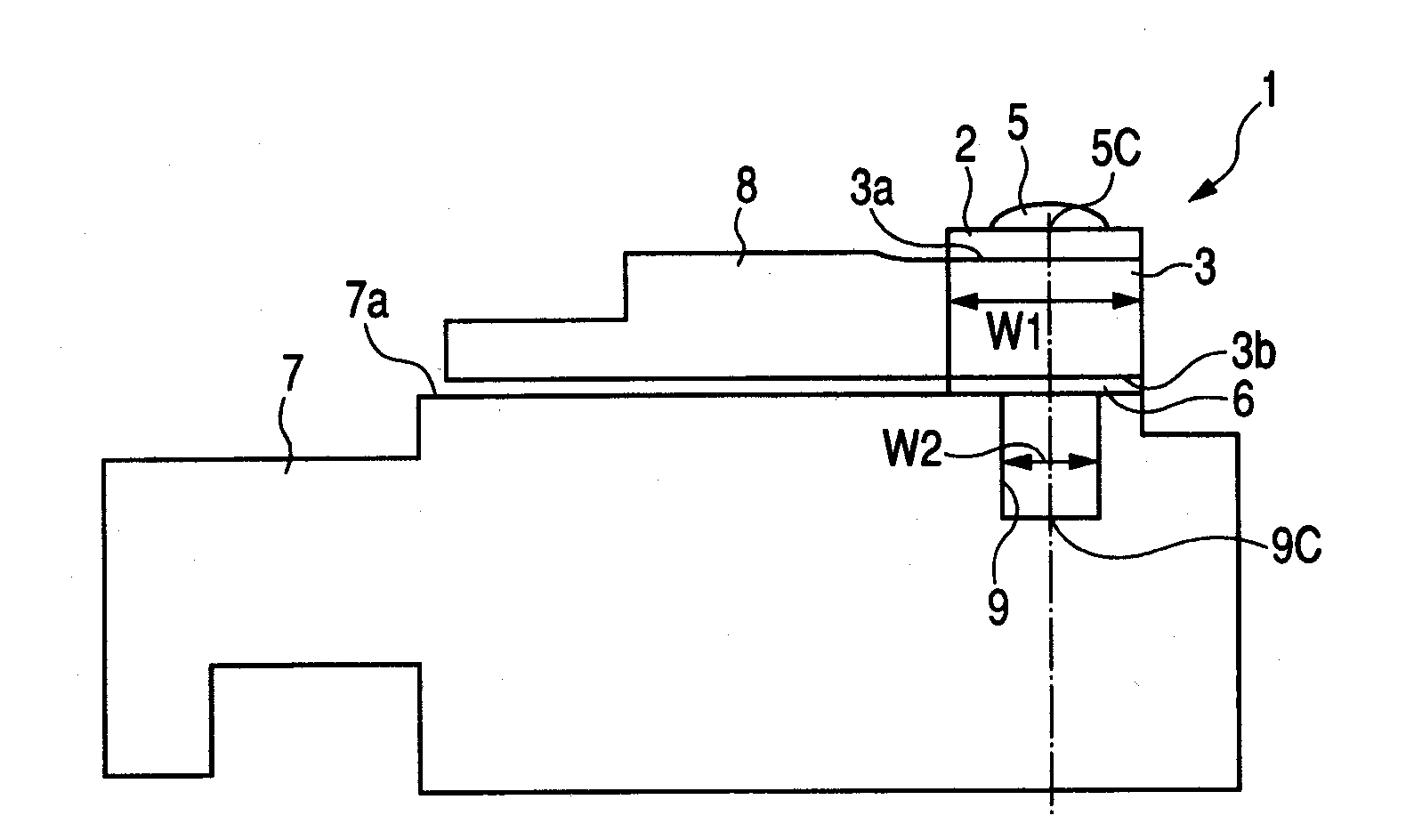
[0024]FIG. 1 is a side view schematically illustrating a thermal head 1 according to an exemplary embodiment. As illustrated in FIG. 1, the thermal head 1 according to the embodiment may have a head substrate 3 made of an insulating material or the like such as a ceramic. A plurality of heating elements 5 arranged in a row may be provided on a surface 3a of the head substrate 3 ...


PUM


Abstract

A thermal head includes: a head substrate including a plurality of heating elements arranged in a row; and a heat dissipation member supporting the head substrate, wherein heat from the heating elements is transferred to the heat dissipation member through the head substrate, a surface of the heat dissipation member opposing the head substrate is provided with a heat accumulation adjusting groove which has a recessed shape along the arrangement direction of the row of the heating elements, and both edge portions of the surface of the heat dissipation member in a width direction of the heat accumulation adjusting groove come in contact with a rear surface of the head substrate opposing the heat dissipation member, the width direction being perpendicular to the arrangement direction of the heating elements.

Description

CROSS REFERENCE TO RELATED APPLICATIONS[0001]The present application contains subject matter related to and claims priority to Japanese Patent Application No. 2009-063213 filed in the Japanese Patent Office on Mar. 16, 2009, the entire contents of which are incorporated herein by reference.BACKGROUND OF THE DISCLOSURE[0002]1. Technical Field[0003]The present disclosure relates to a thermal head in which a head substrate provided with heating elements is mounted to a heat dissipation member.[0004]2. Related Art[0005]In the past, from the standpoint that an improvement in the recording quality of a printer using a thermal head is achieved by properly dissipating heat of heating elements heated when the thermal head is driven, a thermal head having a heat dissipation member for dissipating the heat of the heating elements has been used.[0006]For example, in a thermal head disclosed in Japanese Unexamined Utility Model Registration Application Publication No. 4-126857, heating elements ...

Claims


Application Information

Patent Timeline
Patent Type & Authority Applications(United States)
IPC IPC(8): B41J2/335
CPCB41J2/33535B41J2/33585B41J2/3358
Inventor SASAKI, TSUNEYUKITERAO, HIROTOSHIHOSHINO, HISASHI
Owner ALPS ALPINE CO LTD
Why Eureka
Try Eureka