
Production Line And A Method For Operating A Such

Active Publication Date: 2010-09-23
ABB (SCHWEIZ) AG
View PDF11 Cites 30 Cited by
  • Summary
  • Abstract
  • Description
  • Claims
  • Application Information

AI Technical Summary

Benefits of technology

[0015]By mixing robots and humans as operators for the production line the above described activities that are related to a production line solely operated by robots is to large extent reduced. Due to the close localization of a working station operated by a human and by a robot, respectively the interaction between the robots and the humans facilitate the transfer of the objects from one working station to the other and greatly reduce the engineering required to achieve this. Further, each working station can be optimized in that operations suitable for automation are performed by robots and those suitable to be carried out manually are performed by humans. Very important is that the robot has at least two arms. The multiple arm arrangement allows the robot to operate with a significant lower power on each arm in comparison with a single arm robot working at the same speed. The reason to that is that a multiple arm robot can make moves in parallel affording a much lower speed and kinetic energy build up to complete the same task as a single arm, provided of course that the operation task, e.g. assembly consists of several operations that can be parallelized.
[0040]According to a further preferred embodiment the working stations are controlled regarding safety such that contact between a robot and a human is prevented or such that contact between a robot and a human restricts the action of the robot.

Problems solved by technology

Traditional robot automation in a production line, however face various problems.
It is inflexible and takes a long time to engineer.
If a robot and a human work so close to each other that they are within reach of each other there is a risk that the human might be injured by the robot.
However the localization of the robots and the humans separated far from each other entails drawbacks, such as that a large area is occupied by the production line and that some kind of conveyer means is required.

Method used


Image

  • Production Line And A Method For Operating A Such
  • Production Line And A Method For Operating A Such

Examples


Embodiment Construction

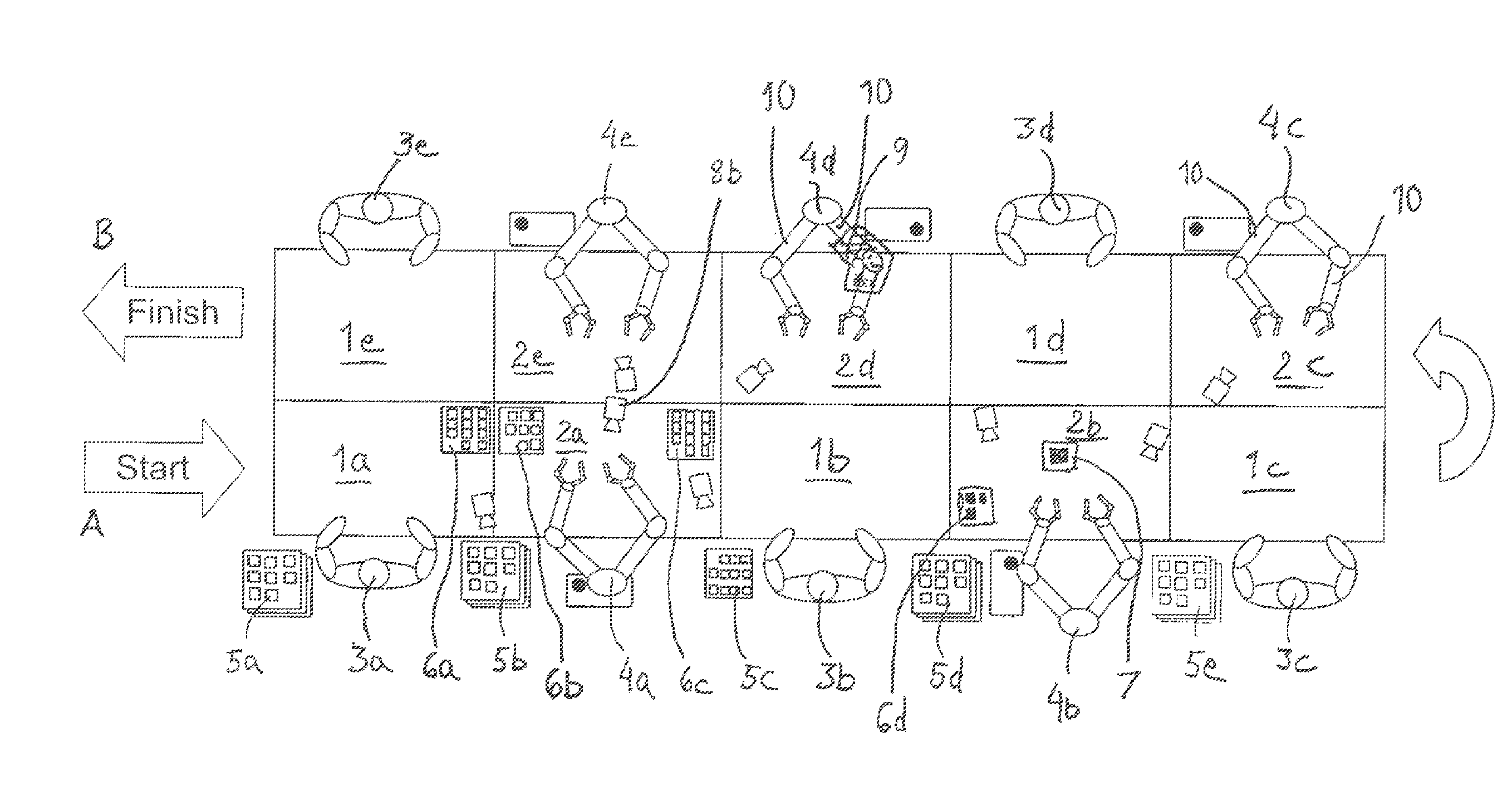
[0045]In the FIGURE a production line according to an example of the invention is schematically illustrated in a view from above. In this example the production line consist of ten working stations 1a-e, 2a-e, arranged in two parallel lines. Each working station is operated either by a human 3a-e such as in working stations 1a-e or by a robot 4a-e such as in working stations 2a-e.

[0046]Objects to be manipulated by the operators, i.e. the human and the robots, reach the production line at arrow A. The objects leave the production line at arrow B. The objects leave the production line either as finished products or as semi-manufactured articles for transport for further operation within the plant or elsewhere.

[0047]Incoming objects are temporarily stored in a first intermediate storage 5a. In this example the first working station 1a is operated by a human 3a. The working step in this first working station might for example be a first assembling operation, where a component from a co...


PUM

PropertyMeasurementUnit
Angleaaaaaaaaaa
Poweraaaaaaaaaa
Softnessaaaaaaaaaa

Abstract

A production line for manipulating objects is provided. The production line has working stations for performing consecutive working steps on the objects by a stationary operator. At least one working station is arranged to be operated by a stationary operator that is a human and at least one working station is operated by a stationary operator that is a robot. The at least one working station being arranged for a stationary operator that is a human and the at least one working station being operated by a stationary operator that is a robot are arranged such that transfer of objects from one working station to the other working station is performed by one or both of the stationary operators. The robot has at least two arms. A method for operating a production line applying a corresponding concept is also provided.

Description

CROSS-REFERENCE TO RELATED APPLICATIONS[0001]The present application is a continuation of pending International patent application PCT / EP2008 / 066676 filed on Dec. 3, 2008 which designates the United States and claims priority from Chinese patent application 200710196589.7 filed on Dec. 5, 2007. The present application is also a continuation of International patent application PCT / EP2007 / 063330 filed on Dec. 5, 2007. The content of all prior applications is incorporated herein by reference.FIELD OF THE INVENTION[0002]The present invention in a first aspect relates to a production line for manipulating objects including a plurality of working stations arranged one after another for performing consecutive working steps on the objects, each working station being arranged for at least one working step by a stationary operator, and at least one working station being arranged for a stationary operator that is a human and at least one working station having a stationary operator that is a r...

Claims


Application Information

Patent Timeline
IPC IPC(8): B23P17/04B25J18/00B25J9/00
CPCB23P21/004H05K13/0053Y10T29/534Y10T29/49829Y10T29/49828Y10T74/20305
Inventor LUNDBERG, IVANKALLMAN, MATSKOCK, SONKE
Owner ABB (SCHWEIZ) AG
Learn More