Imaging device, and method for manufacturing the same

Active Publication Date: 2010-09-23
PANASONIC CORP
View PDF36 Cites 6 Cited by
  • Summary
  • Abstract
  • Description
  • Claims
  • Application Information

AI Technical Summary

Benefits of technology

[0029]The present invention can provide an imaging device and a method for manufacturing the same which can simplify the manufacturi

Problems solved by technology

In addition, in the imaging device 10 in related art, since the lens 11 is fixed to the lens bracket 12 by way of the lower case 22 and the upper

Method used


Image

  • Imaging device, and method for manufacturing the same
  • Imaging device, and method for manufacturing the same
  • Imaging device, and method for manufacturing the same

Examples


Embodiment Construction

[0045]Now, with reference to accompanied drawings, an embodiment of the present invention will be described below.

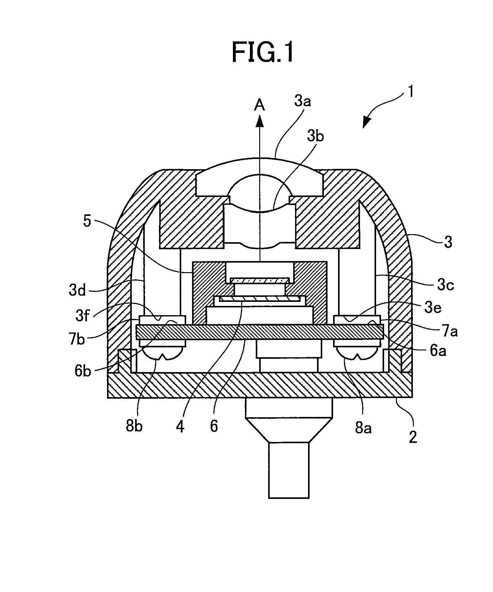
[0046]FIG. 1 is a cross-sectional view of a vehicle-mounted camera 1 in accordance with the embodiment.

[0047]The structure of the vehicle-mounted camera 1 will be described first.

[0048]As shown in FIG. 1, the vehicle-mounted camera 1 according to the present embodiment includes a lower case 2 constituting a part of a body case, an upper case 3 provided with lenses 3a and 3b and constituting the body case integrally with the lower case 2, an imaging element 4, an MID 5 with the imaging element 4 mounted thereon, an MID mounting substrate 6 with the MID 5 mounted thereon, two pieces of substrate mounting bosses 3c and 3d protruding from within the upper case 3 towards the MID mounting substrate 6, spacers 7a and 7b provided between the substrate mounting bosses 3c and 3d and the MID mounting substrate 6, and fixing screws 8a and 8b for securing the MID mounting substrate 6...


PUM

PropertyMeasurementUnit
Thicknessaaaaaaaaaa

Abstract

A vehicle-mounted camera (1) comprises a lower case (2) constituting a part of a case, an upper case (3) provided with lenses (3a, 3b) constituting the case integrally with the lower case (2), an imaging element (4) for converting light passing through the lenses (3a, 3b) into an electrical signal, an MID-mounting substrate (6) with the imaging element (4) mounted, substrate mounting bosses (3c, 3d) for mounting the MID-mounting substrate (6) to the upper case (3), and spacers (7a, 7b) interposed between the MID-mounting substrate (6) and the substrate mounting bosses (3c, 3d) for adjusting the clearance between the lenses (3a, 3b) and the light receiving plane of the imaging element (4), structured to fix the lower case (2) to the upper case (3) while the MID-mounting substrate (6) mounted with the imaging element (4) is being fixed to the upper case (3) by the substrate mounting bosses (3c, 3d).

Description

BACKGROUND[0001]1. Technical Field[0002]The present invention relates to an imaging device and a method for manufacturing the same.[0003]2. Related Art[0004]In recent years, imaging devices have been widely used, for example, in vehicles and mobile phones, and are required to be miniaturized as they become popular. As one way to achieve miniaturization of imaging devices, there is known an imaging device having an imaging element compactly mounted on a circuit board utilizing molded interconnect device (MID) method.[0005]An imaging device of this type known in related art is disclosed in JP-2007-102017, for example, which prevents electrical problems attributed to the condition of the joints between an MID and a circuit board being incomplete when mounting a relatively heavy lens such as a high performance wide-angle lens.[0006]As shown in FIG. 5, an imaging device 10 disclosed in JP-2007-102017 is provided with a lens 11 having a male thread section 11a, a lens bracket 12 having th...

Claims


Application Information

Patent Timeline
IPC IPC(8): H05K3/30
CPCG02B13/001G02B13/003G03B17/02Y10T29/4913H04N5/2253H04N5/2254H04N5/2257H04N5/2251H04N23/54H04N23/57
Inventor INAGAKI, TATSUHIKOIMAI, MAKOTOMIMURA, HIDETOSHI
Owner PANASONIC CORP
Why Eureka
Try Eureka