Aerosol inhalation system

Inactive Publication Date: 2010-09-23
JAPAN TOBACCO INC
View PDF17 Cites 53 Cited by
  • Summary
  • Abstract
  • Description
  • Claims
  • Application Information

AI Technical Summary

Benefits of technology

[0019]As described above, according to the aerosol inhalation system of the invention, when the user inhales through the mouthpiece, the solution in the feed pipette is sucked out from the feed opening into the aerosol-generating passage. The sucked-out solution is exposed to heat from the heating element to be evaporated, and immediately generates aerosol. This dramatically reduces a response

Problems solved by technology

As a result, there is a delay in response from th

Method used


Image

  • Aerosol inhalation system
  • Aerosol inhalation system
  • Aerosol inhalation system

Examples


first embodiment

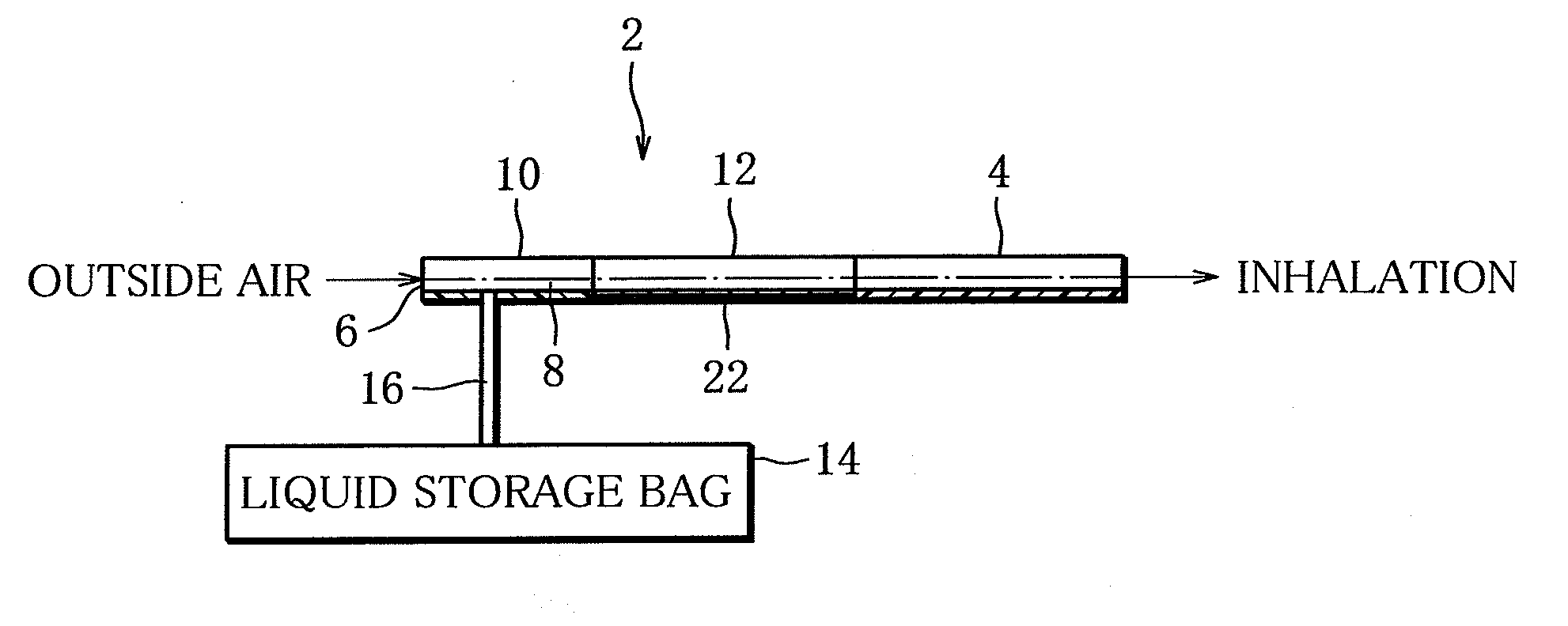
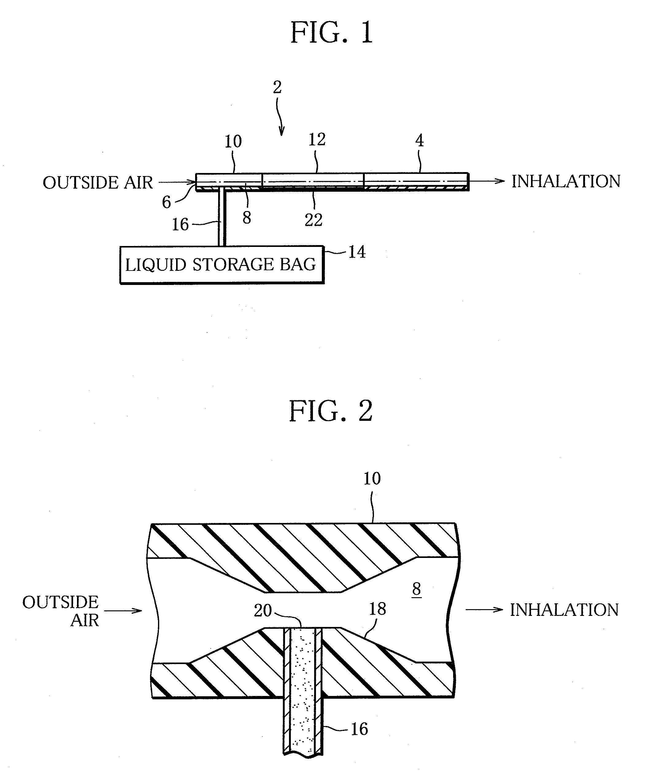
[0039]FIGS. 1 and 2 show an aerosol inhalation system (hereinafter, referred to as a system) of a

[0040]The system includes an inhalator 2. The inhalator 2 as a whole has the shape of a rod. The inhalator 2 has a front end portion, a middle portion and a rear end portion. The rear end portion is formed into a mouthpiece 4. The inhalator 2 further has an outside air inlet 6 in a front end face thereof. The front end portion and the middle portion define an aerosol-generating passage 8 therein. The aerosol-generating passage 8 extends from the outside air inlet 6 to the mouthpiece 4.

[0041]More specifically, the front end and middle portions of the inhalator 2 are made up of an air pipe 10 having the outside air inlet 6 and a tubular heating device, namely, a tubular electric heater 12, respectively. An inner path inside the air pipe 10 and the heater 12 is formed as the aerosol-generating passage 8.

[0042]A flexible liquid storage bag 14 is prepared outside the inhalator 2. The liquid s...

second embodiment

[0052]FIGS. 3 and 4 show a system of a

[0053]In the second embodiment, the inhalator 2 has the air pipe 10 and the mouthpiece 4. The air pipe 10 and the mouthpiece 4 are directly connected to each other without the heater 12 to be interposed therebetween. A plate-like electric heater 24 is contained in the air pipe 10. The electric heater 24 is also a ceramic heater. The electric heater 24 is disposed at predetermined distance away from the feed opening 20 of the feed pipette 16, and is arranged along the aerosol-generating passage 8 within the air pipe 10. To be specific, the electric heater 24 has an upstream end portion facing to the feed opening 20, and extends from the feed opening 20 towards the mouthpiece 4 over predetermined length.

[0054]In the system of the second embodiment, too, the user's inhalation sucks the solution out of the feed opening 20 into the air pipe 10, and the sucked-out solution is transferred towards the mouthpiece 4 together with an intake airflow. In thi...

third embodiment

[0055]FIGS. 5 and 6 show a system of a

[0056]The system of the third embodiment differs from that of the first embodiment only in that a ring-shaped orifice member 26 is detachably fitted to the front end of the air pipe 10, namely, the outside air inlet 6. The orifice member 26 has an orifice 28 smaller than a diameter of the outside air inlet 6. During the user's inhalation, the orifice 28 regulates an intake rate of the outside air flowing into the aerosol-generating passage 8 through the outside air inlet 6, and determines negative pressure produced near the feed opening 20. In other words, the opening degree of the orifice 28 determines the amount of the solution sucked out from the feed opening 20 of the feed pipette 16, or aerosol generation amount, per inhalation by the user.

[0057]It is therefore desirable that the opening degree (diameter) of the orifice member 26 should be variable as shown by a chain double-dashed line in FIG. 6. In this case, the amount of the solution su...


PUM


Abstract

An aerosol inhalation system has an inhalator (2) having an aerosol-generating passage (8) connecting an outside air inlet (6) and a mouthpiece (4) to each other, in which a part of the passage (8) is made up of a tubular electric heater (12); a flexible storage bag (14) prepared separately from the inhalator (2) and containing a solution that is a source of aerosol; and a feed pipette (16) connecting the bag (14) to the inhalator (2), in which the feed pipette (16) has a feed opening (20) opened in the passage (8) and disposed upstream of the heater (12), the solution in the bag (14) is sucked out of the feed opening (20) into the passage (8) and then transferred to the heater (12) with an intake airflow running towards the mouthpiece (4) when the user inhales, the sucked-out solution is heated by the heater (12) to be evaporated, and aerosol is thus generated in the intake airflow.

Description

TECHNICAL FIELD[0001]The present invention relates to an aerosol inhalation system for feeding a user with medical products, items of taste and the like in an aerosol form.BACKGROUND ART[0002]An aerosol inhalation system of this type is disclosed, for example, in Kohyo (National Publication of Translated Version) No. 2000-510763. The system disclosed in the publication has a supply pump for supplying a solution (liquid substance) that is a source of aerosol. The supply pump is connected to a pipe. The pipe has an open end, and is filled inside with a solution supplied from the supply pump. A mouthpiece is disposed adjacently to the pipe end of the pipe. An electric heater is arranged so as to surround the pipe end portion of the pipe. The electric heater heats and evaporates the solution existing in the pipe end portion. The vapor of the solution is spontaneously emitted from the pipe end. Such solution vapor is condensed to produce aerosol when exposed to air that is inhaled by the...

Claims


Application Information

Patent Timeline
IPC IPC(8): A61M11/00
CPCA61M11/041A61M11/042
Inventor YAMADA, MANABUKATAYAMA, KAZUHIKOSASAKI, HIROSHI
Owner JAPAN TOBACCO INC
Why Eureka
Try Eureka