Plastic waveguide slot array and method of manufacture

a technology of waveguides and arrays, applied in the direction of slot antennas, linear waveguide fed arrays, antennas, etc., can solve the problems of high manufacturing costs, surface roughness of internal surfaces of channels becoming critical issues,

Inactive Publication Date: 2010-09-23
UNIVERSTIY OF CALIFORNIA +1
View PDF7 Cites 35 Cited by
  • Summary
  • Abstract
  • Description
  • Claims
  • Application Information

AI Technical Summary

Benefits of technology

[0007]The substrate can have a step surface that aids in aligning the slot plate with the waveguide channel, the slot plate being at least partially in contact with the step surface when attached to the substrate. In some instances, the step surface is a recess that is adjacent to and surrounds the waveguide channel and the slo

Problems solved by technology

As higher frequencies are propagated through the waveguide channel and inlet channel, the surface roughness of the internal surfaces of the channels becomes a critical

Method used


Image

  • Plastic waveguide slot array and method of manufacture
  • Plastic waveguide slot array and method of manufacture
  • Plastic waveguide slot array and method of manufacture

Examples


Embodiment Construction

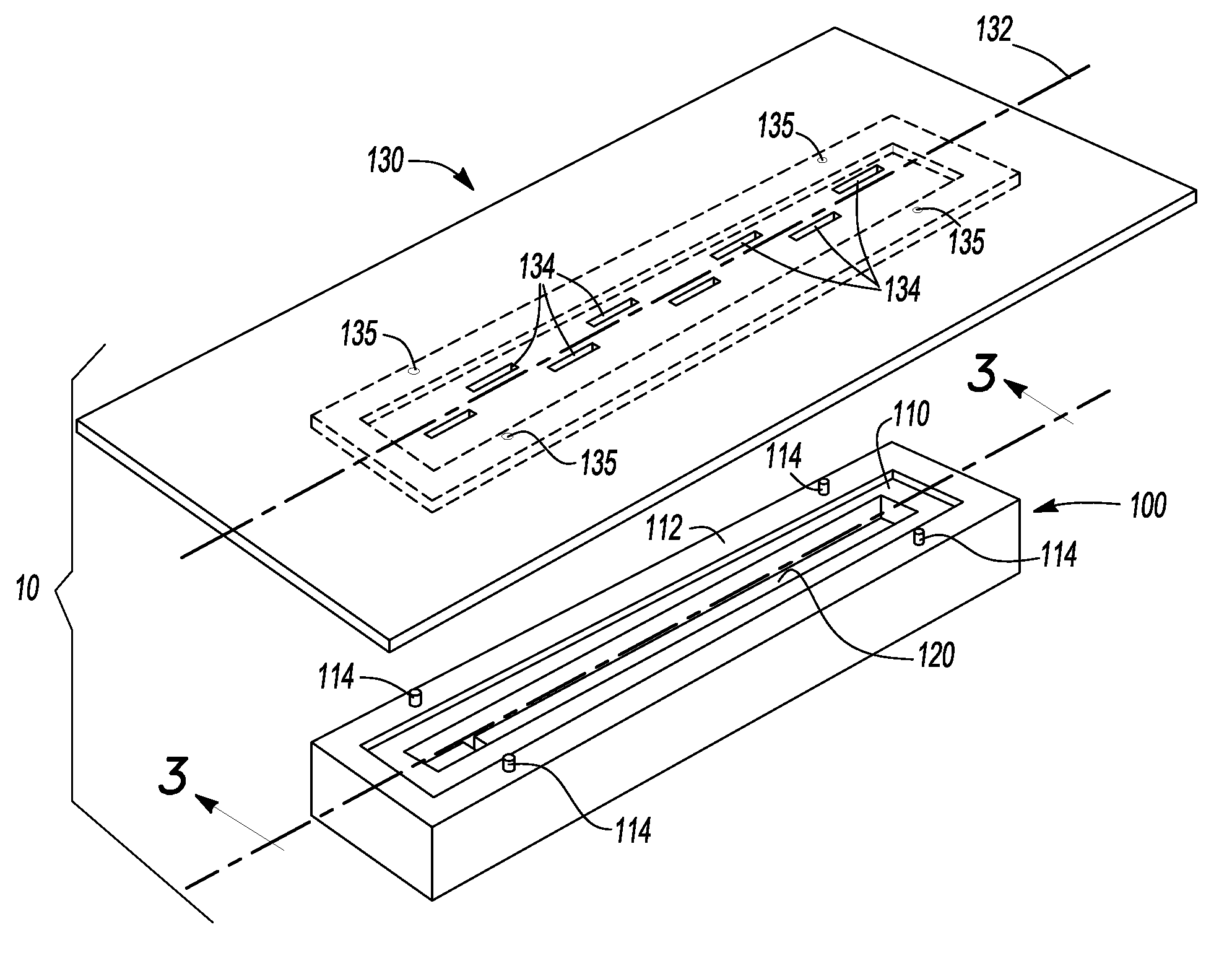
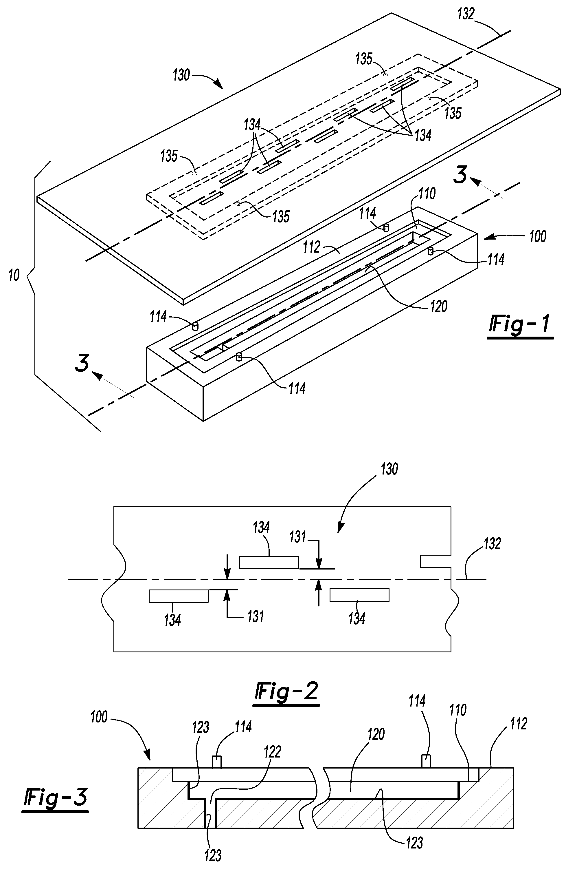
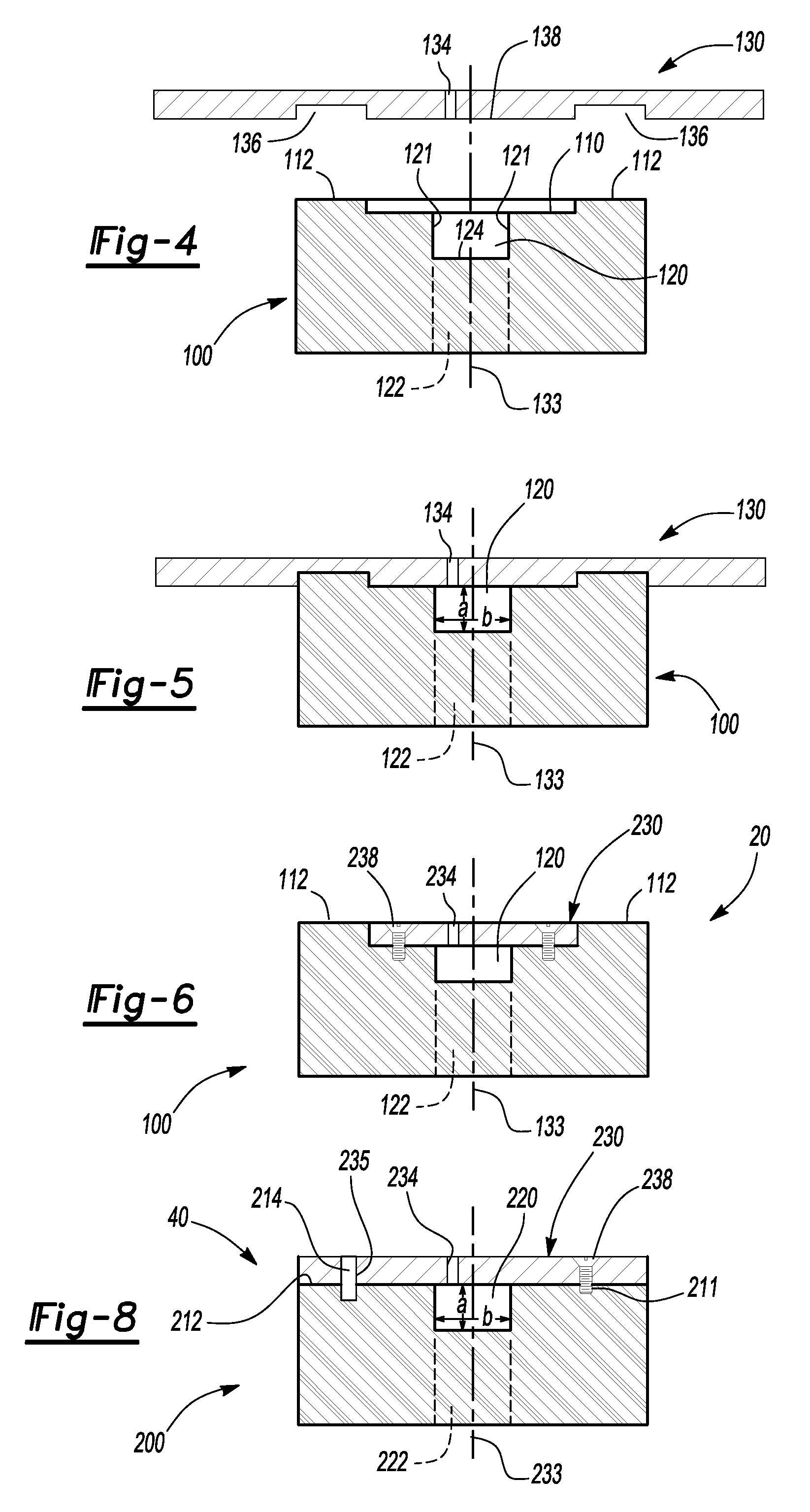
[0022]The present invention discloses a waveguide antenna structure and a method of manufacture. As such, the waveguide antenna structure has utility as a component for a long-range radar.

[0023]The waveguide antenna structure can include a non-metallic substrate having a waveguide channel extending along a first direction and an inlet channel extending along a second direction. In some instances, the non-metallic substrate is an elongated substrate and the first direction is a longitudinal direction and the second direction is a transverse direction of the elongated substrate. The inlet channel intersects the waveguide channel and both channels are at least partially coated with a metallic material. In some instances, the inlet channel, also known as the inlet port or input port, is integral with the non-metallic substrate and is made or formed when the waveguide channel is made / formed, e.g. during a one-shot injection molding process.

[0024]The waveguide channel can have a generally...


PUM

PropertyMeasurementUnit
Electromagnetic waveaaaaaaaaaa
Widthaaaaaaaaaa
Metallic bondaaaaaaaaaa

Abstract

The present invention discloses a waveguide antenna structure and a method of manufacture. The waveguide antenna structure can include a non-metallic substrate having a waveguide channel extending along a first direction and an inlet channel extending along a second direction. The inlet channel intersects with the waveguide channel and both channels are at least partially coated with a metallic material. The waveguide channel can have a generally U-shaped cross-section with an open side that is at partially enclosed by a slot plate that is attached to the non-metallic substrate.

Description

FIELD OF THE INVENTION[0001]The present invention is related generally to a waveguide slot array, and in particular, to a waveguide slot array made from plastic.BACKGROUND OF THE INVENTION[0002]Waveguide antennas having slots to serve as radiating and / or receiving elements are known. Within the waveguide antennas is a waveguide channel through which electromagnetic waves are propagated. On one face of the waveguide channel, slots are typically present through which the electromagnetic waves can be transmitted and / or received.[0003]The design and structure of a particular waveguide antenna is dictated to a large extent by the frequency of electromagnetic waves that are to be transmitted and / or received. In addition, particular frequency's or range of frequencies have selective uses. For example, 22 GHz, 30 GHz and 40 GHz frequencies are reserved for military applications, the 60 GHz frequency is used for Internet wireless local area networks (LAN) and the range of 63-1000 GHz frequen...

Claims


Application Information

Patent Timeline
IPC IPC(8): H01Q13/10H01P11/00
CPCH01Q13/22Y10T29/49016H01Q21/0087H01Q21/005
Inventor FUH, MICHAEL YIIN-KUENMARGOMENOS, ALEXANDROSLIN, LIWEI
Owner UNIVERSTIY OF CALIFORNIA
Why Eureka
Try Eureka