Liquid droplet ejecting head and image forming apparatus

a technology of image forming apparatus and droplet ejection head, which is applied in the direction of printing and inking apparatus, etc., can solve the problems of disturbance of ink flow rate, non-ejection of ink to unintended direction, and inability to supply ink, etc., and achieve the effect of preventing or suppressing air bubbles

Inactive Publication Date: 2010-09-23
FUJIFILM CORP
View PDF3 Cites 65 Cited by
  • Summary
  • Abstract
  • Description
  • Claims
  • Application Information

AI Technical Summary

Benefits of technology

[0010]In view of the above-described circumstances, the present invention provides a liquid droplet ejecting head which is capable of efficiently removing air bubbles while maintaining liquid circulation efficiency, and also provide an image forming apparatus.

Problems solved by technology

Conventionally, in an inkjet head, when air bubbles are mixed in a pressure chamber, inconveniences such as ejection to unintended direction caused by dispersion of ejection pressure, non-ejecting by ink non-supply, and the like occur.
Further, in an inkjet system, if unintended air bubbles remain in a supply passage, disturbance occurs in flow rate of ink and there is a possibility that the properties of ink may change depending on the circumstances.
However, in the structure described in patent document 1, before ink in an ink tank is supplied to a head main body, the ink is made to flow into the upper reservoir provided in a reservoir unit separated from the head main body, so as to remove air bubbles, thereby resulting in a complicated structure and deterioration in circulation efficiency of the ink.
Therefore, the structure of this apparatus is complicated and the cost thereof increases.
Further, the ink flow path is switched between the time of forming an image and the time of circulation recovery, thereby resulting in deterioration of circulation efficiency of the ink.

Method used


Image

  • Liquid droplet ejecting head and image forming apparatus
  • Liquid droplet ejecting head and image forming apparatus
  • Liquid droplet ejecting head and image forming apparatus

Examples


second embodiment

[0094]FIG. 6 shows the structure of an inkjet line head according to a second embodiment of the present invention. Note that the same members as those of the first embodiment are denoted by the same reference numerals, and a description thereof is omitted.

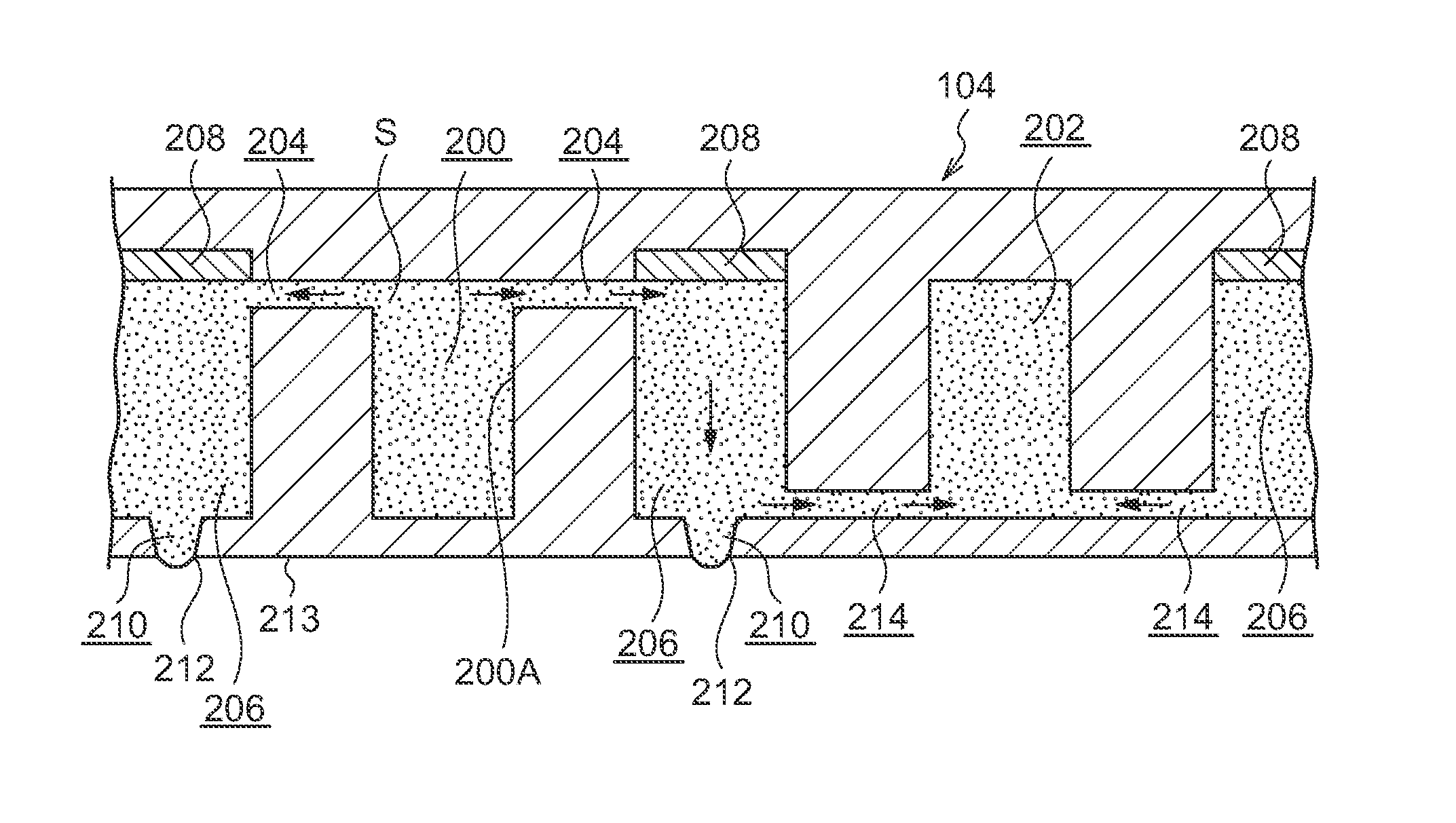
[0095]As shown in FIG. 6, the structure in which the supply-side common flow channels 200 and the circulation-side common flow channels 202 are alternately provided in the head plate 230 used for the inkjet line heads is similar to the structure of the first embodiment.

[0096]Plural bypass flow channels 232 each connecting the supply-side common flow channel 200 and circulation-side common flow channel 202, which are disposed adjacent (next) to each other, are provided at the distal end portion 200B of the supply-side common flow channel 200 and a longitudinal-direction intermediate portion of the supply-side common flow channel 200. The plural bypass flow channels 232 are each disposed in inclined direction with respect to the long...

third embodiment

[0098]FIG. 7 shows the structure of an inkjet line head according to a third embodiment of the present invention. Note that the same members as those of the first and second embodiments are denoted by the same reference numerals, and a description thereof is omitted.

[0099]As shown in FIG. 7, the structure in which the supply-side common flow channels 200 and the circulation-side common flow channels 202 are alternately provided on the head plate 240 used for the inkjet line heads is similar to the structure of the first embodiment.

[0100]A bypass flow channel 242 is provided at the distal end portion 200B of the supply-side common flow channel 200. The bypass flow channel 242 connects the supply-side common flow channel 200 to the circulation-side common flow channel 202 which is disposed adjacent (next) thereto. The bypass flow channel 242 is formed such that the cross-sectional area thereof gradually becomes smaller toward the circulation-side common flow channel 202 side.

[0101]By ...


PUM


Abstract

A liquid droplet ejecting head capable of efficiently removing air bubbles while maintaining liquid circulation efficiency, and an image forming apparatus are provided. Plural supply-side common flow channels and circulation-side common flow channels are disposed alternately, and plural pressure-chambers that each communicates with the supply-side common flow channel via an ink supply channel are provided. The plural pressure-chambers each communicates with the circulation-side common flow channel via an ink circulation channel. A bypass flow channel, connecting the supply-side common flow channel and the circulation-side common flow channel disposed adjacent thereto, and flowing the ink from the supply-side common flow channel to the circulation-side common flow channel, is provided at an end portion at the most downstream side of the supply-side common flow channel. Thus, air bubbles remaining in the supply-side common flow channel flows into the circulation-side common flow channel through the bypass flow channel together with the ink.

Description

CROSS-REFERENCE TO RELATED APPLICATION[0001]This application claims priority under 35 USC 119 from Japanese Patent Application No. 2009-065863 filed Mar. 18, 2009, the disclosure of which is incorporated by reference herein.BACKGROUND OF THE INVENTION[0002]1. Technical Field[0003]The present invention relates to a liquid droplet ejecting head and an image forming apparatus.[0004]2. Related Art[0005]Conventionally, in an inkjet head, when air bubbles are mixed in a pressure chamber, inconveniences such as ejection to unintended direction caused by dispersion of ejection pressure, non-ejecting by ink non-supply, and the like occur. Further, in an inkjet system, if unintended air bubbles remain in a supply passage, disturbance occurs in flow rate of ink and there is a possibility that the properties of ink may change depending on the circumstances. In an inkjet recording apparatus, a structure in which air bubbles remaining in ink are removed is proposed.[0006]Japanese Patent Applicati...

Claims


Application Information

Patent Timeline
Patent Type & Authority Applications(United States)
IPC IPC(8): B41J2/175
CPCB41J2/1404B41J2202/12B41J2/1634B41J2/14145B41J2/14233B41J2002/14419B41J2002/14459B41J2/18
Inventor YAMAMOTO, TEPPEI
Owner FUJIFILM CORP
Why Eureka
Try Eureka