System for Cooling an Electronic Display

a technology for electronic displays and cooling systems, applied in lighting and heating apparatus, cathode-ray/electron beam tube circuit elements, instruments, etc., can solve the problems of a large amount of heat produced by illumination devices such as ccfl assemblies, leds, organic leds, etc., and become a significant source of hea

a technology for electronic displays and cooling systems, applied in lighting and heating apparatus, cathode-ray/electron beam tube circuit elements, instruments, etc., can solve the problems of a large amount of heat produced by illumination devices such as ccfl assemblies, leds, organic leds, etc., and become a significant source of hea

US20100238394A1Active Publication Date: 2010-09-23MFG RESOURCES INT INC

Image

  • System for Cooling an Electronic Display
  • System for Cooling an Electronic Display
  • System for Cooling an Electronic Display

Examples


Embodiment Construction

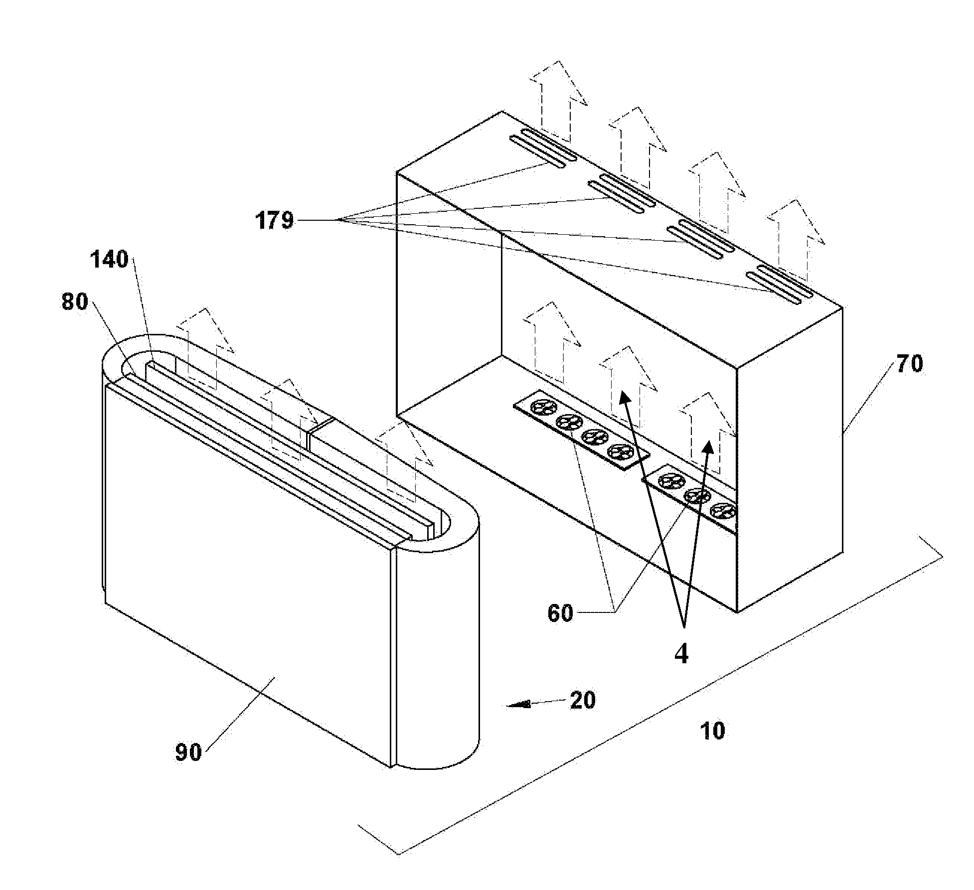
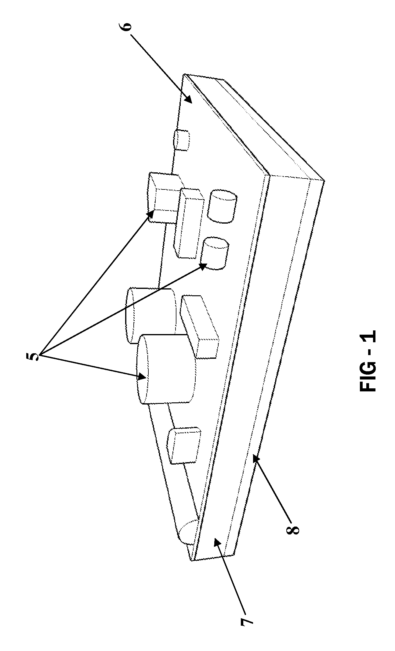
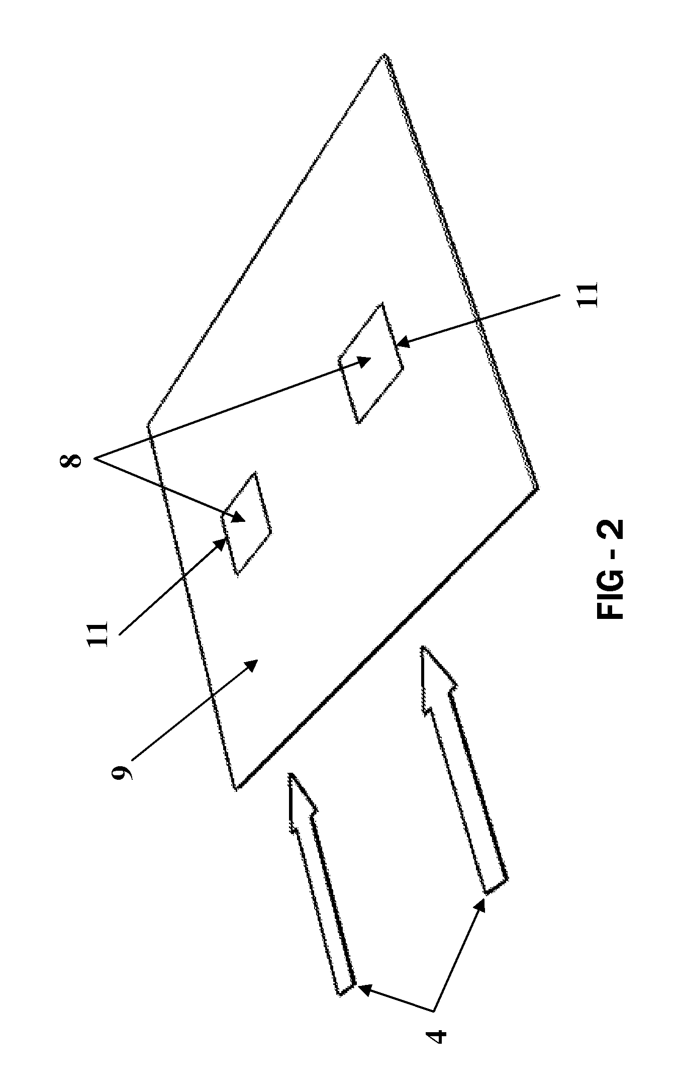
[0007]Exemplary embodiments relate to a system for cooling the following portions of an electronic display, either alone or in combination: (1) power module(s), (2) backlight, and (3) front display surface. Power modules with heat dissipating assemblies (ex. cold plates and / or heat sinks) may be used with some embodiments where the side of the power module containing the heat dissipating assembly is placed in the path of moving air while the side of the power module containing sensitive electrical components remains in a separate environment. An isolating structure may provide the necessary gaseous isolation between the two sides of the power modules.

[0008]Backlights with a front and rear sides may be used with some embodiments where the front side contains the illumination devices and the rear side contains a metallic surface for dissipating the heat from the illumination devices. Ideally, there should be a low level of thermal resistance between the front and rear sides of the bac...


PUM


Abstract

A system for cooling an electronic display where an isolating structure may be used to allow ambient air to cool power modules. The isolating structure substantially prohibits containments which may be present within the ambient air from contacting sensitive electrical components on the power modules or otherwise. A gasket may be used to seal the interface between the power modules and the isolating structure. Heat sinks may be placed in thermal communication with the power supplies and fans may draw air through a narrow channel in which the heat sinks are located. In some embodiments the narrow channel may have the opposing surface of the channel defined by the rear portion of an LED assembly. Exemplary embodiments may use the ambient air to cool both the power modules and a closed loop of isolated gas within the electronic display.

Description


Claims


Application Information

Patent Timeline
23 Sep 2010
Publication
US20100238394A1