Developing device, image forming device and image forming method

a technology of developing device and image forming device, which is applied in the direction of instruments, electrographic process devices, optics, etc., can solve the problems of fogging and insufficient suppression effect of the fluctuation of the electrification amount of each toner, and achieve excellent image quality

Inactive Publication Date: 2010-09-23
SEIKO EPSON CORP
View PDF14 Cites 6 Cited by
  • Summary
  • Abstract
  • Description
  • Claims
  • Application Information

AI Technical Summary

Benefits of technology

[0018]Further, the toner carrying roller may be made of a metal in which the surface is subject to amorphous plating treatment. In this toner carrying roller, it is clarified by the experiments of the inventors that the toners can be satisfactorily frictionally electrified in the housing. By combining this toner carrying roller with the restriction blade applied with the restriction bias voltage, the properties of the toners carried on the toner carrying roller surface are satisfactorily maintained and an excellent image quality can be obtained.
[0019]Further, it is desirable that the content r...

Problems solved by technology

In this type of technique, since there is an unavoidable fluctuation in electrification amounts of the toners, in particular, the toner having a low electrification amount and the toner electrified with the polarity opposite to the original electrification polarity are attached to a portion of the image to which the toner should not be naturally attached, leading the so-called fogging.
As a result, the amount of toner to which the electric charge should be injected is increased and the overall electrification amount is increased, but an effect of suppres...

Method used


Image

  • Developing device, image forming device and image forming method
  • Developing device, image forming device and image forming method
  • Developing device, image forming device and image forming method

Examples


Embodiment Construction

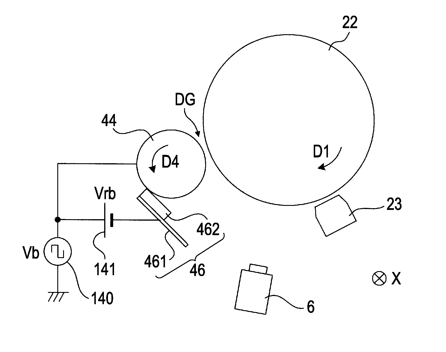
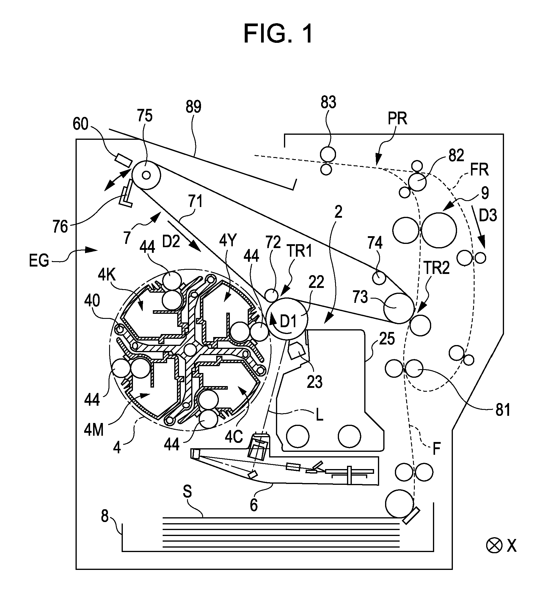
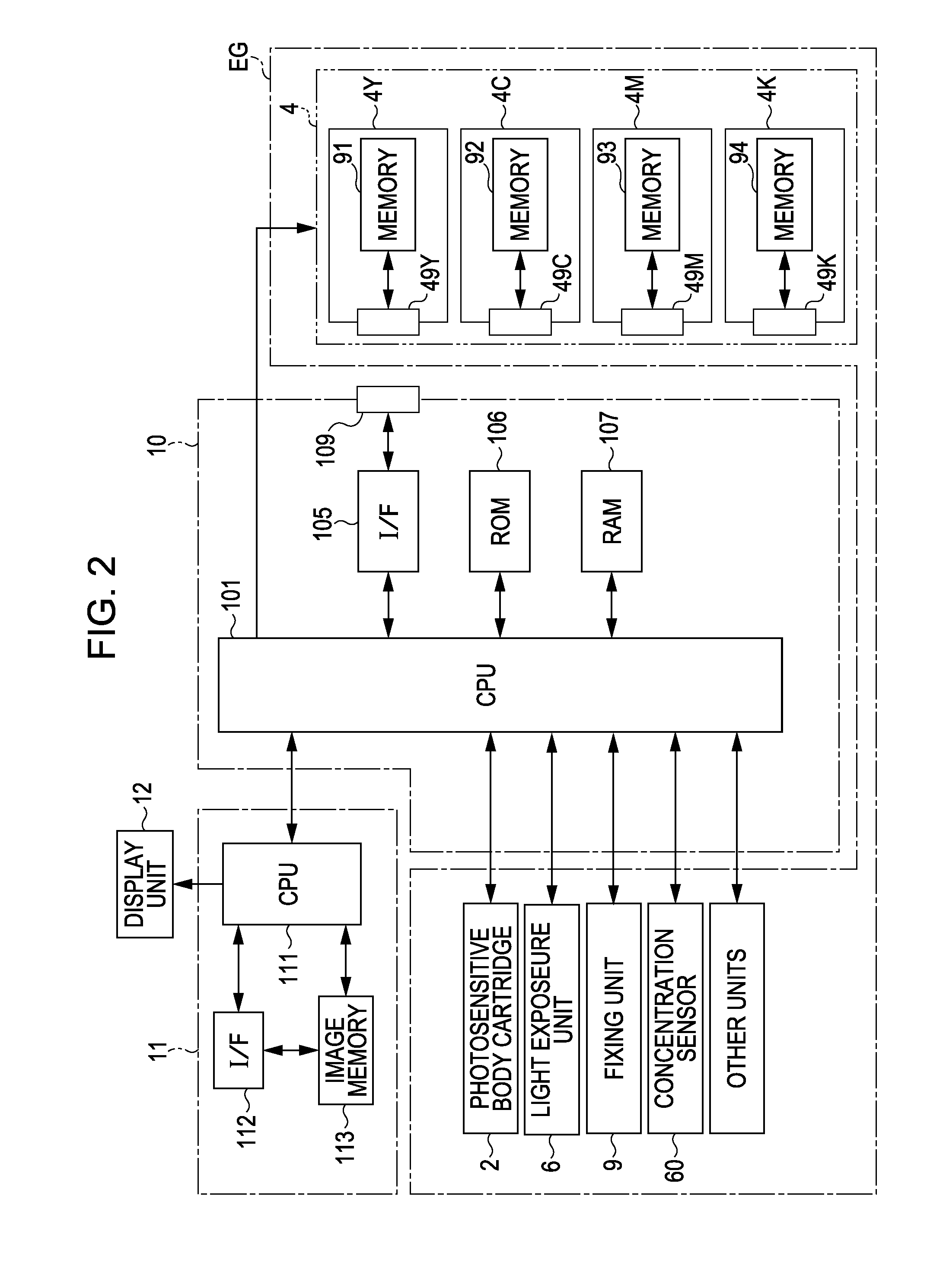
[0034]FIG. 1 shows one embodiment of an image forming device to which the invention is applied. Further, FIG. 2 is a block diagram illustrating the electric structure of the image forming device in FIG. 1. This device is the image forming device in which toners (developing agents) of four colors of yellow (Y), cyan (C), magenta (M) and black (K) are overlapped to form a full color image, or, a monochrome color image is formed using only the toner of black (K). In this image forming device, when an image signal from an external device such as a host computer is supplied to a main controller 11, a CPU 101 mounted on an engine controller 10 controls each portion of an engine portion EG according to commands from the main controller 11 to perform a predetermined image forming operation and forms the image corresponding to the image signal on a sheet S.

[0035]In the engine portion EG, a photosensitive body 22 is placed so as to be rotatable in arrow direction D1 in FIG. 1. Further, an ele...


PUM


Abstract

A development device includes a housing having toner housed therein; a toner carrying roller that has a plurality of convex portions and concave portions surrounding the convex portions, formed on a surface thereof; and a conductive restriction blade in which a free end or an adjoining region adjacent to the free end abuts the surface of the toner carrying roller, thereby restricting the amount of the toner carried on surface of the toner carrying roller, wherein the toner has an external additive including a metal oxide, the restriction blade is applied with a restriction bias voltage of the same polarity as the regular electrification polarity of the toner, and a gap between the front end of the free end and the convex portion of the toner carrying roller is smaller than a volume average particle diameter of the toner.

Description

BACKGROUND[0001]1. Technical Field[0002]The present invention relates to a developing device having a toner carrying roller in which a convex portion and a concave portion are arranged on its surface, an image forming device and an image forming method for forming an image using the roller.[0003]2. Related Art[0004]In the technique for developing an electrostatic latent image by means of toners, generally, the toners are carried on a surface of a toner carrying roller formed approximately in the cylindrical shape. In this type of technique, since there is an unavoidable fluctuation in electrification amounts of the toners, in particular, the toner having a low electrification amount and the toner electrified with the polarity opposite to the original electrification polarity are attached to a portion of the image to which the toner should not be naturally attached, leading the so-called fogging. Thus, in order to increase the electrification amount of the toner carried on the toner ...

Claims


Application Information

Patent Timeline
IPC IPC(8): G03G15/08
CPCG03G15/0812
Inventor YAMADA, YOICHIARUGA, TOMOHIROMATSUMOTO, DAISUKEKITAZAWA, ATSUNORIKOBASHI, MASARU
Owner SEIKO EPSON CORP
Why Eureka
Try Eureka