Controlled Placement and Orientation of Nanostructures

a nanostructure and positioning technology, applied in the field of nanostructure positioning and orientation on substrates, can solve the problems of limiting compatibility with substrate materials or other system components, limiting chemistry, and unable to produce very high-quality multi-walled carbon nanotubes, etc., and achieve precise, yet complex positioning of nanostructures.

Active Publication Date: 2010-09-23
RGT UNIV OF CALIFORNIA
View PDF16 Cites 19 Cited by
  • Summary
  • Abstract
  • Description
  • Claims
  • Application Information

AI Technical Summary

Benefits of technology

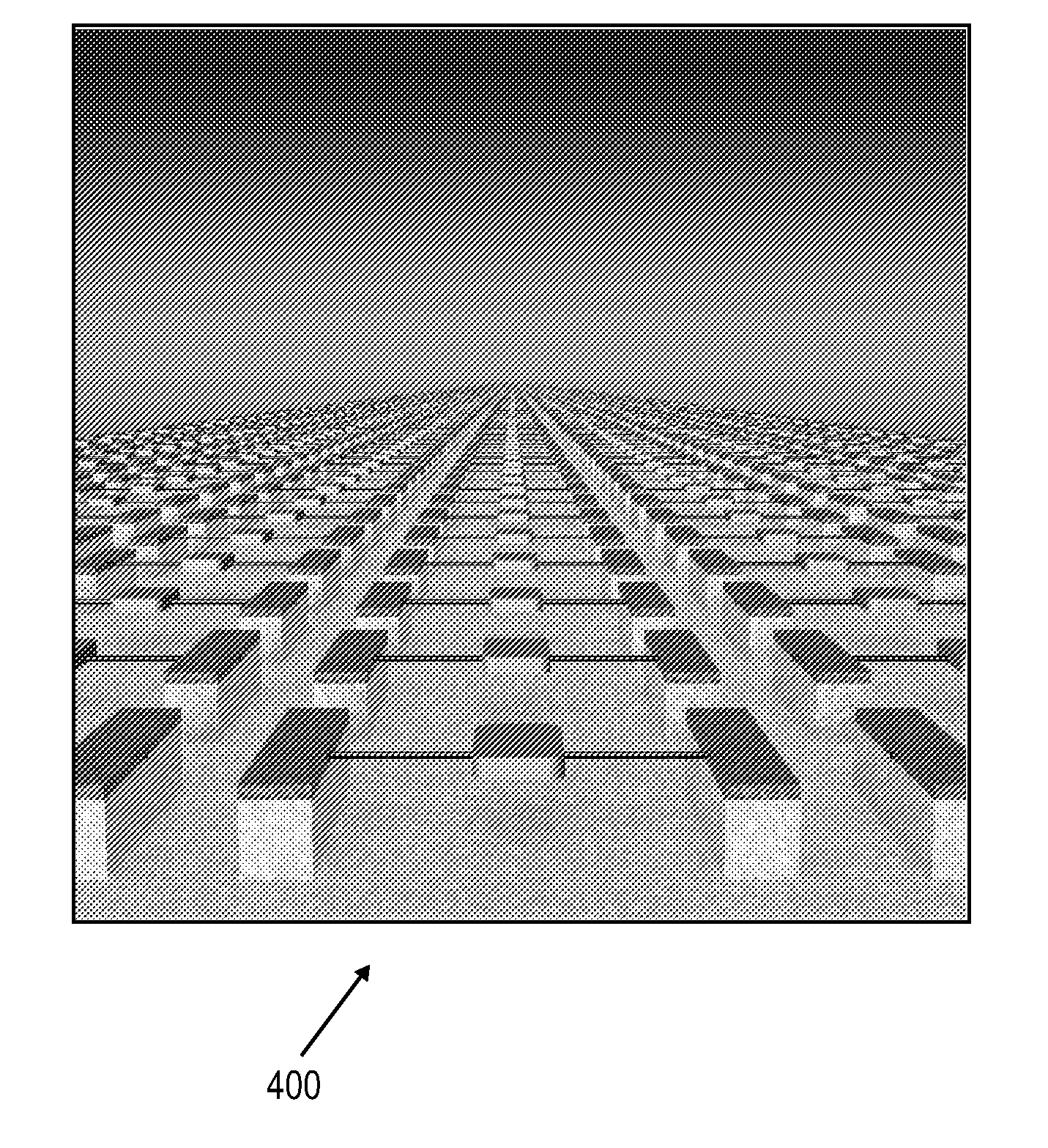
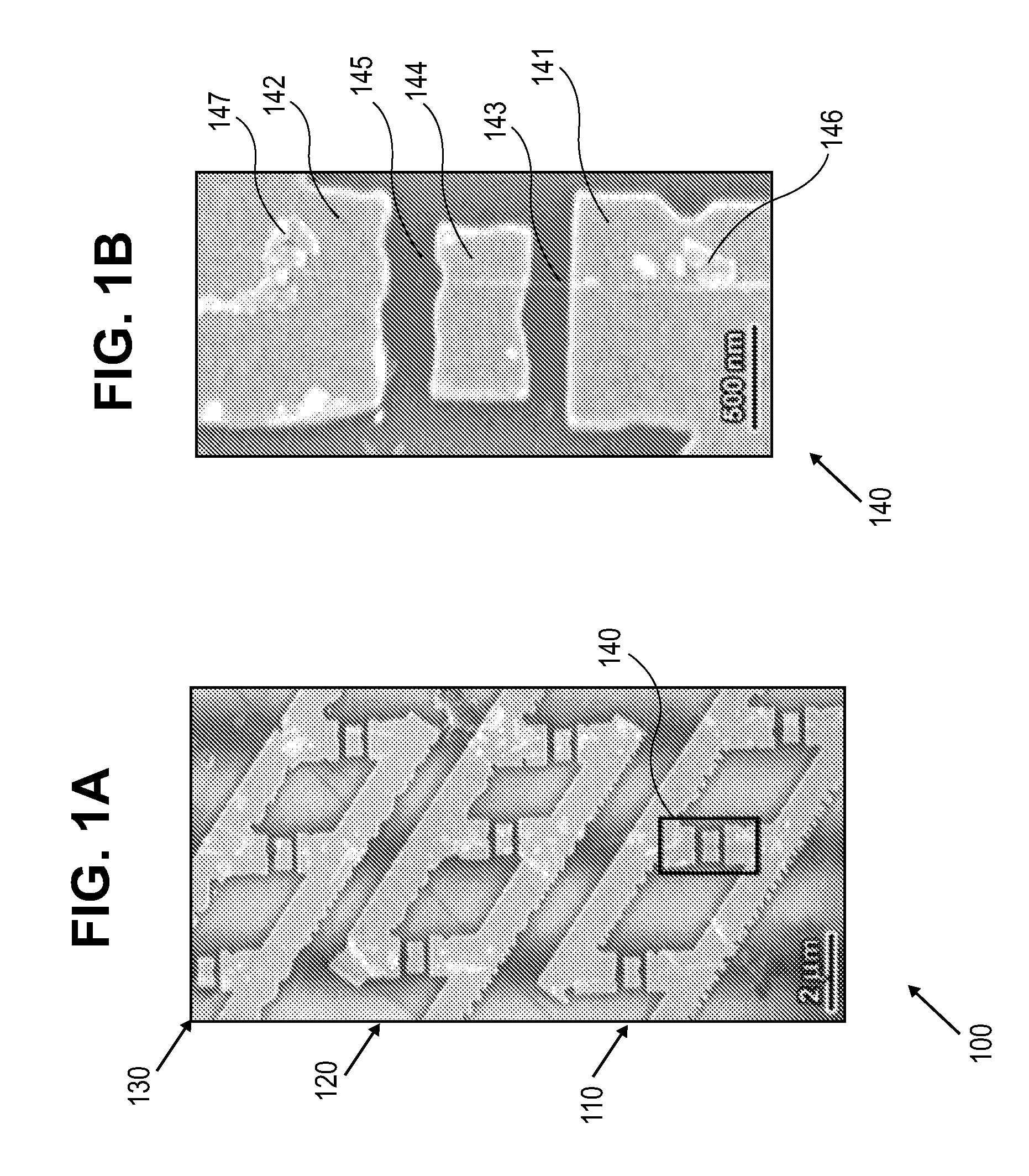
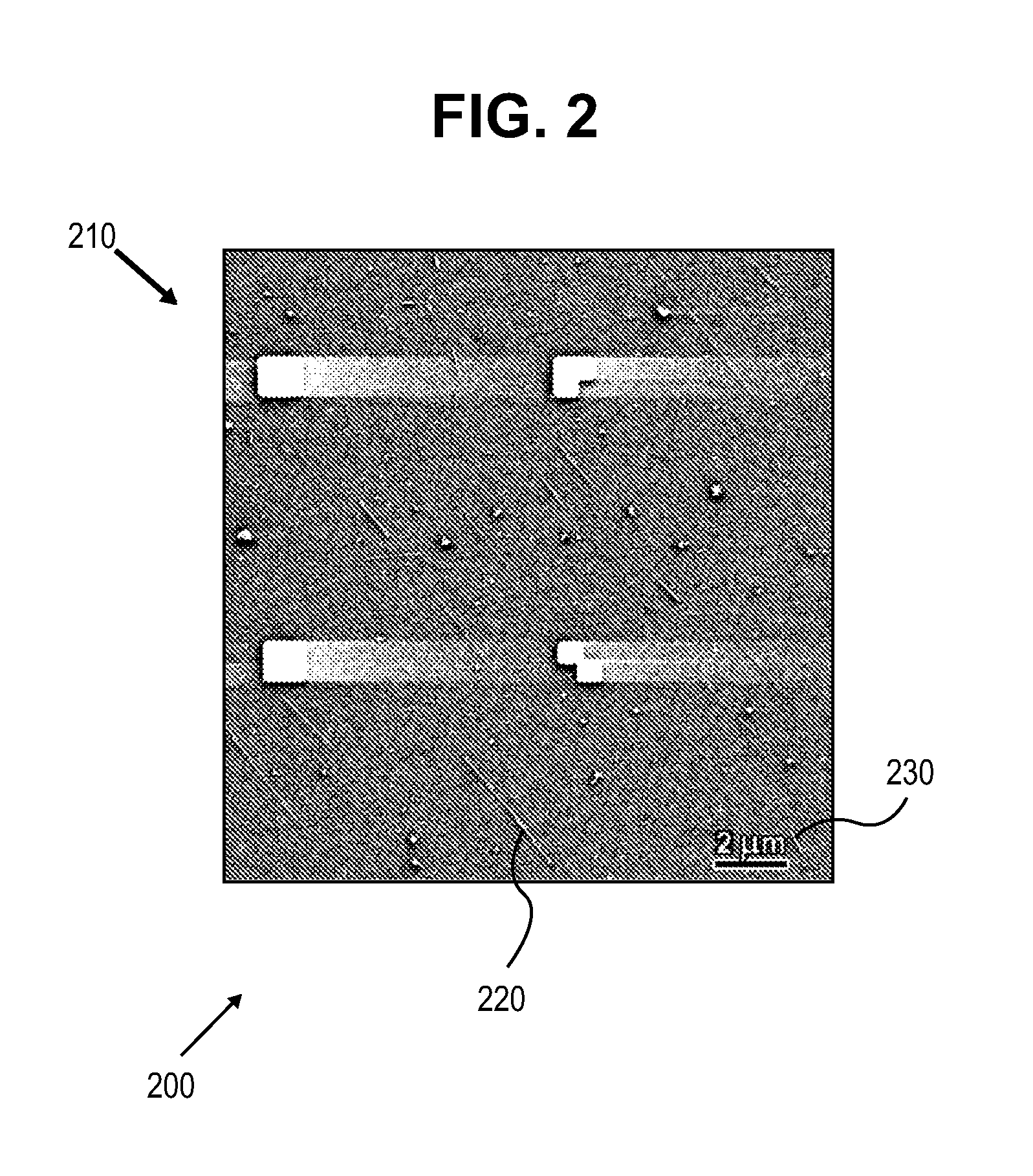
[0023]The thin layer of polymer coating is preferably provided by a resist composition that can be chemically altered by incident radiation. This permits lithographic patterning of the layer, which can achieve a precise, yet complex positioning of nanostructures. Further, the orientation of deposited nanostructures may be controlled by controlling the flow of the solvent suspension. The substrate can be any material which can support nanostructures. Preferably the substrate is silicon which can be etched and processed with various layers according to known semiconductor manufacturing techniques.

Problems solved by technology

A fundamental challenge in the development of NEMS arrays (and of nanotube- and nanowire-based devices in general) is the large-scale controlled placement of molecular sized building blocks on a substrate.
Unfortunately, such methods are unable to produce very high quality multi-walled carbon nanotubes as are often required for NEMS applications2, 4.
Furthermore, CVD is commonly a high temperature process, which severely limits compatibility with substrate materials or other system components.
Unfortunately nearly all of these methods necessitate rather complex substrate topology or involved and limiting chemistry.

Method used


Image

  • Controlled Placement and Orientation of Nanostructures
  • Controlled Placement and Orientation of Nanostructures
  • Controlled Placement and Orientation of Nanostructures

Examples


Embodiment Construction

Definitions

[0037]Nanostructure means a nanoelectromechanical device that comprises one or more elements having at least one characteristic minimum dimension of less than or equal to 200 nm, and may be exemplified, without limitation, by components including one or more of: a nanotube; a nanowire; a nanorod; a noncrystalline or amorphous nanostructure; a nanocrystal; a supramolecular structure (i.e., a structure comprised of multiply-conjoined molecular and atomic units); a single walled carbon nanotube; a multiwalled carbon nanotube; a stripped (extendable) multiwalled carbon nanotube; a carbon nanowire; a carbon nanosheet; a carbon nanobelt; a carbon nanotube bundle; a boron-nitride nanotube; a silicon nanotube; a silicon nanobelt; a silicon nanowire; a compositionally modulated silicon nanowire; and a silicon nanosheets. Without limitation, some nanostructures act as nanomotors, nanomechanical resonators, nanobeam deflectors, sensors, actuators, device components, etc. Nanostruct...


PUM

PropertyMeasurementUnit
thicknessaaaaaaaaaa
resonance frequenciesaaaaaaaaaa
concentrationaaaaaaaaaa

Abstract

A method for controlled deposition and orientation of molecular sized nanoelectromechanical systems (NEMS) on substrates is disclosed. The method comprised: forming a thin layer of polymer coating on a substrate; exposing a selected portion of the thin layer of polymer to alter a selected portion of the thin layer of polymer; forming a suspension of nanostructures in a solvent, wherein the solvent suspends the nanostructures and activates the nanostructures in the solvent for deposition; and flowing a suspension of nanostructures across the layer of polymer in a flow direction; thereby: depositing a nanostructure in the suspension of nanostructures only to the selected portion of the thin layer of polymer coating on the substrate to form a deposited nanostructure oriented in the flow direction. By selectively employing portions of the method above, complex NEMS may be built of simpler NEMSs components.

Description

CROSS-REFERENCE TO RELATED APPLICATIONS [0001]This utility patent application claims benefit of priority to U.S. provisional patent application 60 / 711,481, filed Aug. 25, 2005, which is hereby incorporated by reference in its entirety.STATEMENT OF GOVERNMENTAL SUPPORT [0002]This invention was made during work supported by U.S. Department of Energy under Contract No. DE-AC02-05CH11231. The government has certain rights in this invention.REFERENCE TO SEQUENCE LISTING OR COMPACT DISK [0003]NoneBACKGROUND OF THE INVENTION [0004]1. Field of the Invention[0005]The present invention generally relates to the field of nanostructure positioning and orientation on substrates, and more particularly to the field of molecular sized nanoelectromechanical systems (NEMS).[0006]2. Related Art[0007]US PG PUB 20030190278 “Controlled deposition of nanotubes” discloses methods for depositing nanotubes.[0008]Diehl et al. “Self-assembled, deterministic carbon nanotube wiring networks,” Angew. Chem. Int. Ed...

Claims


Application Information

Patent Timeline
Patent Type & Authority Applications(United States)
IPC IPC(8): B05D3/12D01F9/12B05D3/00
CPCB82B3/00Y10T428/24132B82Y30/00B82Y40/00
Inventor ZETTL, ALEX K.YUZVINSKY, THOMAS D.FENNIMORE, ADAM M.
Owner RGT UNIV OF CALIFORNIA
Why Eureka
Try Eureka