Light Based Projectile Detection System for a Virtual Firearms Training Simulator

a projectile detection and virtual firearms technology, applied in the direction of target detectors, weapons, aiming means, etc., can solve the problems of unrealistic recoil action for users, simulation lacks credibility for users, and does not produce a realistic experience for users

Inactive Publication Date: 2010-09-23
MEGGITT TRAINING SYST
View PDF5 Cites 11 Cited by
  • Summary
  • Abstract
  • Description
  • Claims
  • Application Information

AI Technical Summary

Benefits of technology

[0008]The system may additionally include a housing to support the screen, with the light source surrounded by the housing and screen to control the distribution of light from said light source. In such an embodiment, a reflective panel (such as paper with foil on one side) may be mounted in said housing diagonally, with the light source positioned between the reflective panel and the screen. This arrangement will project light directly onto the distal side of the screen as well as onto the reflector panel, which will assist in evenly projecting light on the distal side of the screen.

Problems solved by technology

A drawback to this system is that the simulated weapon operated by the user often simply generates a laser pulse to imitate the firing of the weapon, which does not produce a realistic experience for the user.
That is, the simulated weapon typically does not have the feel of an actual firearm, and often does not produce recoil action, or produces unrealistic recoil action for the user, such that the simulation lacks credibility for the user.
Consequently, trainees that are not used to extensive target practice with live firearms may be disadvantaged when required to handle firearms in combat situations.
Since a bullet is not a pulse of light, the camera detection method described above may not seem practical to use.
While all of these methods may work to some degree, none of them are performed within desired parameters, such as at a low financial cost and having a high degree of accuracy.

Method used


Image

  • Light Based Projectile Detection System for a Virtual Firearms Training Simulator
  • Light Based Projectile Detection System for a Virtual Firearms Training Simulator
  • Light Based Projectile Detection System for a Virtual Firearms Training Simulator

Examples


Embodiment Construction

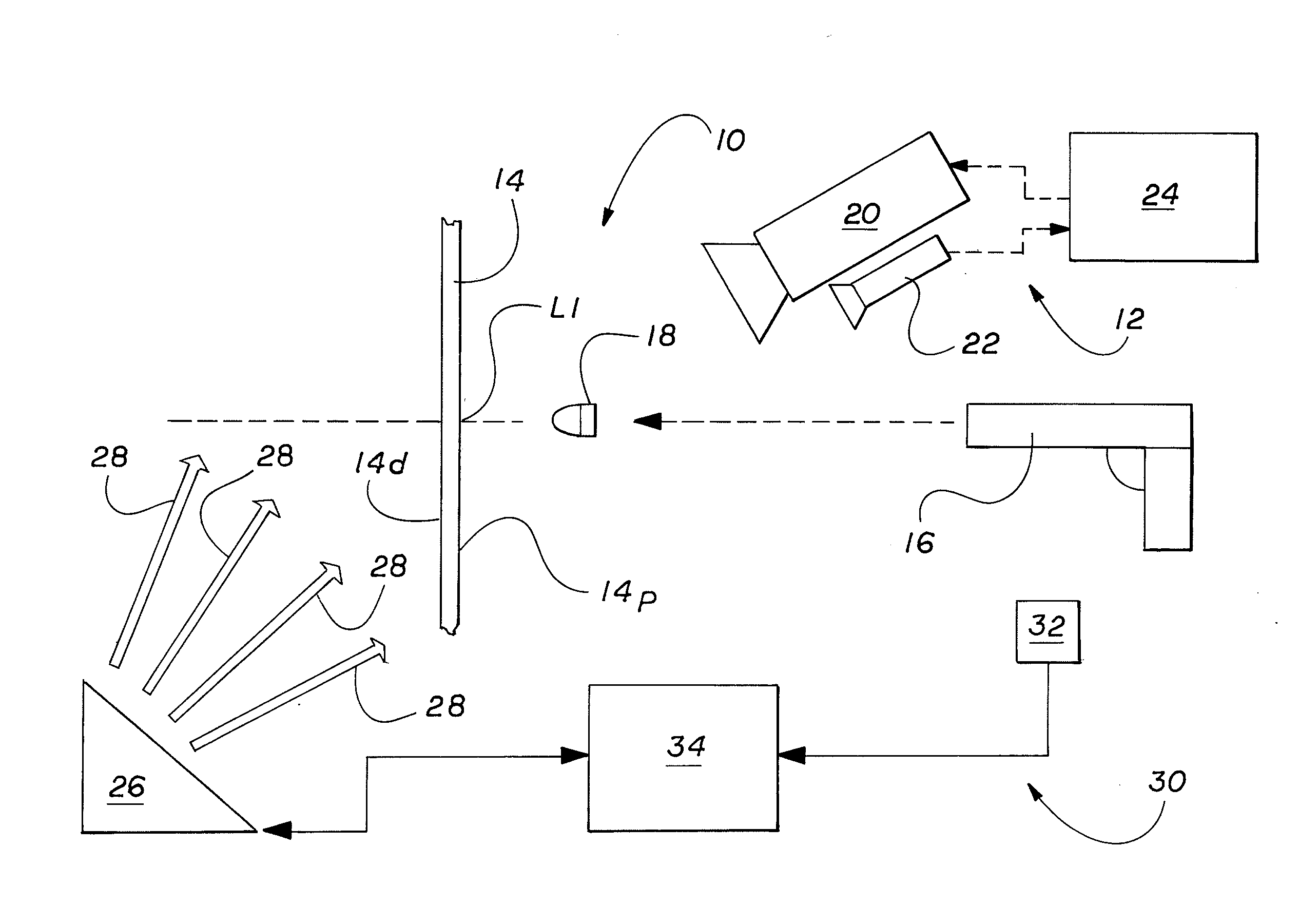
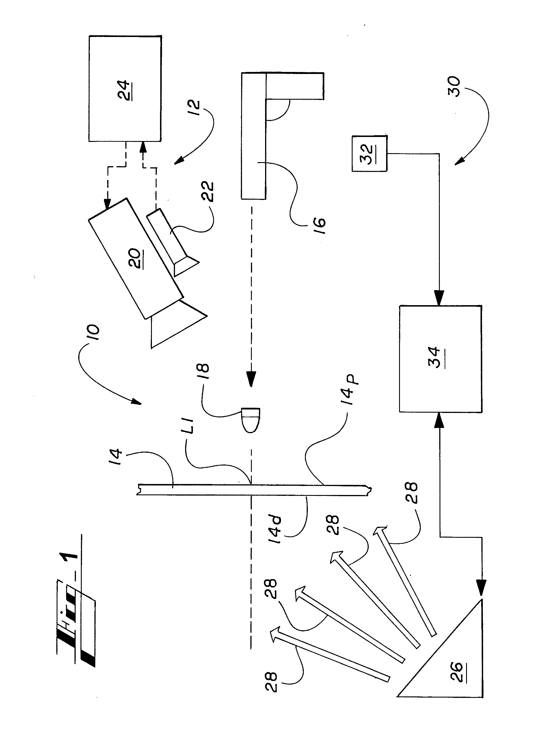
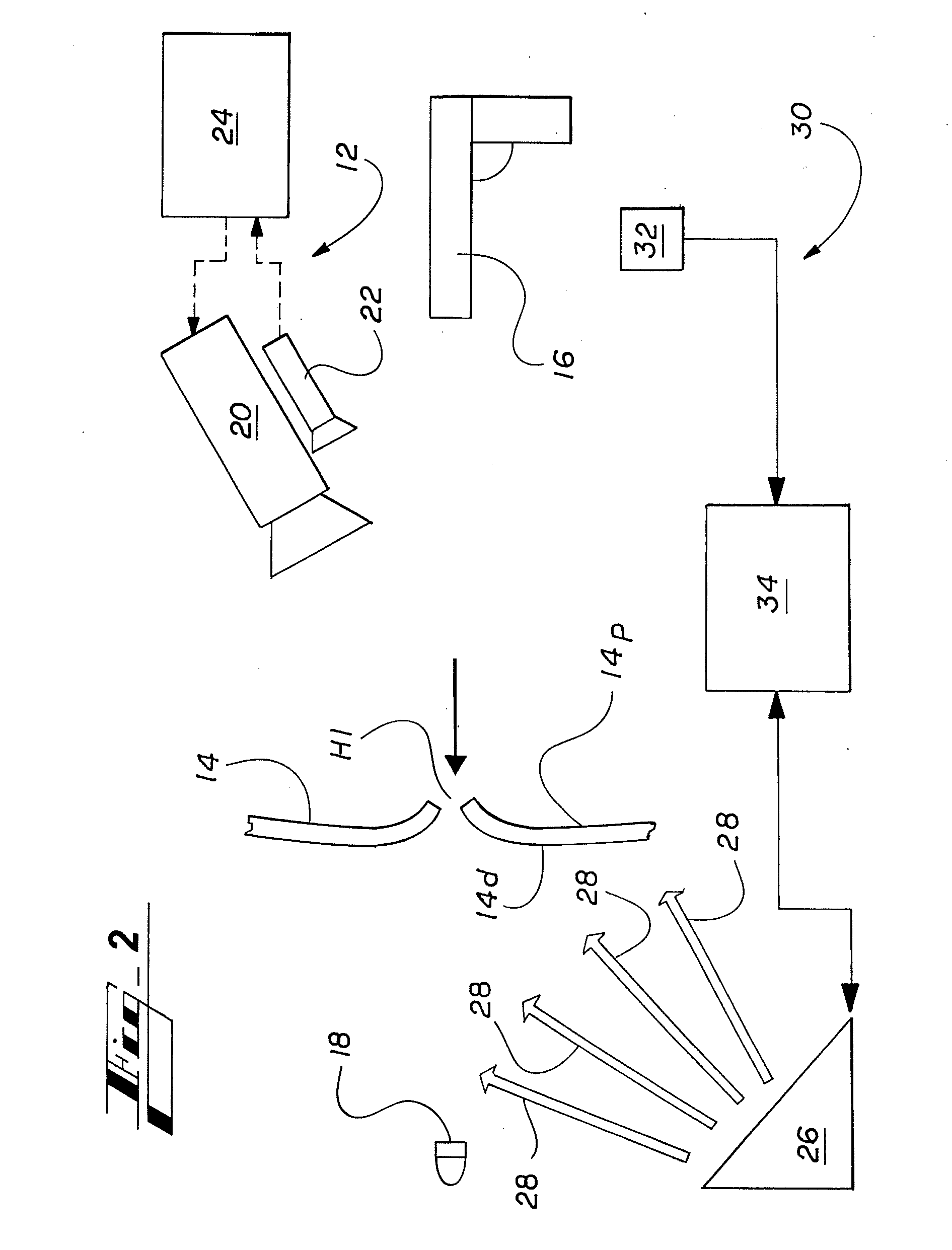
[0012]Referring to FIGS. 1-3, a light based projectile detection system 10 is illustrated. The light based projectile detection system 10 is able to monitor the impact of a projectile 18 fired by an actual firearm 16 on a self-sealing screen 14 using a laser detection system 12 similar to those described above and as used in a typical laser-based virtual firearms training simulator known in the art.

[0013]More specifically, the laser detection system 12 includes a scenario projector 20 and a camera 22 that are both in electrical communication with a simulation or hit detect computer 24. The projector 20 may include any type of image-generating device, and receives a simulation scenario from the hit detect computer 24. The projector 20 will then broadcast that scenario on one or more self-sealing screens 14. In contrast, the camera 22 monitors the self-healing screen 14 for a light or laser pulse, which will correspond to the point of impact of the projectile 18 fired in during the si...


PUM


Abstract

A light based projectile detection system for use with a firearm and a virtual firearms training simulator includes a self-sealing screen having a proximal side and a distal side. A scenario projector transmits a simulation onto the proximal side, and a light source faces the distal side. The light source selectively projects light onto the distal side of the screen when the firearm is shot, such that light from the source traverses the screen after contact by a projectile. A camera monitors the light traversing the aperture created by the projectile to determine and associate the position of impact and transmit that information to a scenario computer. The system may include an audio detection circuit to monitor the sound generated by the firearm and transmit a signal to a flash controller to cause the light source to illuminate. The screen will then re-seal around the hole so that the light no longer traverses the screen.

Description

CROSS REFERENCE TO RELATED PATENT APPLICATIONS[0001]This application claims priority from co-pending U.S. Provisional Application Ser. No. 61 / 162,498, filed on Mar. 23, 2009, said application being relied upon and incorporated herein by reference.FIELD OF INVENTION[0002]The present invention relates to a system and method for determining the actual coordinates of a projectile impact in a screen and associating the point of impact with a firearms training simulation.BACKGROUND OF THE INVENTION[0003]A typical virtual firearms training simulator uses simulated weapons that do not fire real bullets to train students on the proper handling of a weapon during a simulated real life scenario. The training scenario includes a video, digital animation, or other virtual scenario of one or more situations requiring the user to react quickly and decisively, such as a hostage scenario, terrorist attack, or general malfeasance. This scenario is projected onto a screen using a video projector, with...

Claims


Application Information

Patent Timeline
Patent Type & Authority Applications(United States)
IPC IPC(8): F41G3/26
CPCF41J5/10F41G3/2694
Inventor CHUNG, BOBBY HSIANG-HUAVACELUKE, BRIAN RONALD
Owner MEGGITT TRAINING SYST
Why Eureka
Try Eureka